1. Board and motor setup
Configure the motors before mechanical assembly, while you can connect them individually. Each arm has its own set of IDs 1–6; do not combine both arms on one bus.
1. Control board
- Identify the USB-C, power and motor-bus connectors on the board.
- Use a data-capable USB cable to connect the board to the computer. USB carries commands; motor power requires a separate supply.
- The red indicator shows board power; green or blue indicates communication. The first motor connects to the board and the remaining motors form a chain.
2. Motor communication and unique IDs
- Each motor has two connectors for the chain: board → motor 1 → motor 2 → … → motor 6.
- Each motor needs its own ID from 1 to 6. The ID determines which motor responds to a command.
- Factory IDs may be identical. Configure motors individually in Lab before assembly, rather than connecting all unconfigured motors at once. IDs remain stored after power is switched off.
3. Assign IDs in Lab
- For the follower shown in the video, prepare six C018 motors and the 12 V supply. Check your own kit labels before connecting power.
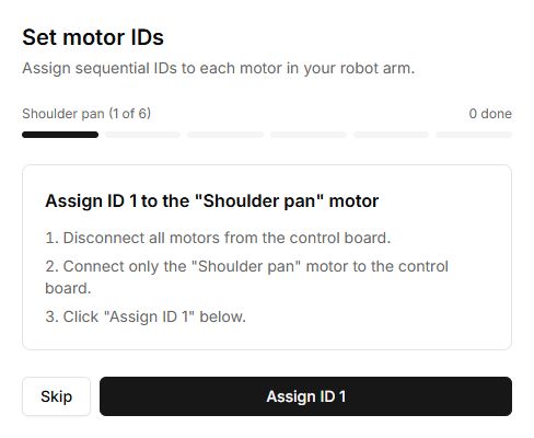
- Lay out and label motors 1–6. Connect only the first motor to the board.
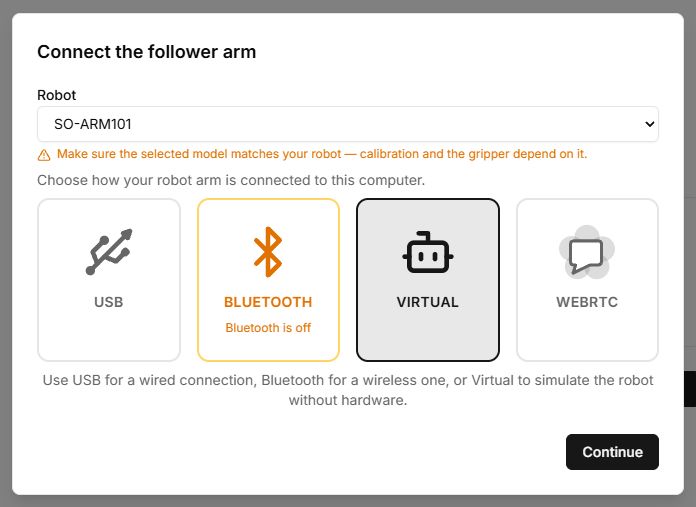
- Open Set motor IDs, choose Connect hardware, select the matching model and USB port, then press Configure for the required motor.
- Wait for Configured. Switch off power, disconnect that motor and connect the next one. Repeat for all six, keeping each ID matched to its motor.
- Configure the leader separately with the appropriate supply and motor types. The leader assembly page lists their joint assignments.
Open the ID tool
Set motor IDs → Connect hardware. Select the matching model: SO-ARM101 and SO-ARM101-Robonine are separate options. Choose USB and the board port to configure physical motors.
Before assembly
- All six motors are configured, with no duplicate IDs within one arm.
- Each motor is labelled with its ID.
- Leader motor types match the assignment table.