Building an Open Source arm. Gripper
 13102
13102
I want to share some details about how the development of our affordable manipulator is progressing. Right now, we’re actively preparing for the assembly stage of the first prototype of the robotic arm.
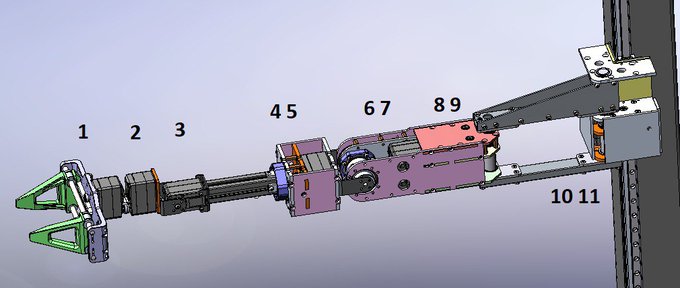
7DOF Robotic Arm
We’ve set ourselves quite an ambitious goal: to achieve specifications comparable to leading research-grade manipulators — 650 mm in length, 7 degrees of freedom, up to 3 kg payload capacity, and positioning accuracy within 1 mm. All source files and developments will be made publicly available — or almost all, depending on the level of support we receive from the robotics community.
What is Gripper
The first thing we’re ready to share is the gripper.
Description: A gripper is a mechanical or robotic device designed to grasp, hold, manipulate, or transport objects. It serves as the “hand” or end-effector of a robotic arm or automation system, allowing the robot to interact with the physical world by gripping and releasing objects.
The gripper is available as open source on GitHub.
We considered many design options for the gripper and ultimately chose a parallel-jaw mechanism. The criteria we used in selecting the design were:
- Simplicity of construction
- Ability to grasp round objects
- Ability to pick up flat objects from a tabletop
- Minimal use of servos
- Cost and reliability of the design
Single-Jaw Rotating Gripper
Probably one of the simplest gripper designs we came across — the Single-Jaw Rotating Gripper — is a configuration where one jaw is fixed and the other is mounted directly on the shaft of a servo motor.
Single-Jaw Rotating Gripper (3d view)
- The downside of this solution is that the front edge of the moving jaw follows an arc. So, if we need to grasp a small object with the tips of the gripper, we have to account for the fact that the object must be positioned along that arc trajectory during closing.
- A second drawback is that, since only one jaw moves, the maximum width of the object that can be gripped is limited by the range of that single moving jaw. To grip the same volume as a parallel gripper, the jaws need to be significantly longer.
Comparison of the jaw length. Single-jaw rotating gripper vs parallel gripper
- The third drawback is that this type of gripper is asymmetric, meaning the center of mass is always shifted toward the moving side.
Taking all these drawbacks of the Single-Jaw Rotating Gripper into account, we decided to explore symmetric parallel gripper designs instead.
Four-Bar Linkage Parallel Gripper vs Parallel Gripper
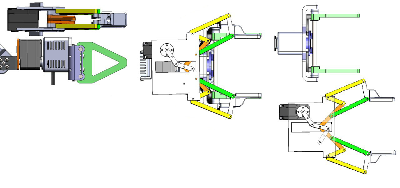
Four-Bar Linkage Parallel Gripper vs Parallel Gripper
The image above shows two versions of a parallel-jaw gripper using a single servo motor. The Four-Bar Linkage Parallel Gripper, where the jaws open at an angle, turns out to be noticeably more complex in terms of the number of parts and overall size.
We could have continued optimizing that design, but we decided that a parallel gripper is simpler to assemble, and therefore would also be cheaper to manufacture.
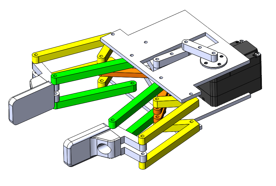
Crank-Rocker Linkage Mechanism
Crank-Rocker Linkage Mechanism
The next important question was the choice of the sliding mechanism. The first option proposed by the engineer was the Crank-Rocker Linkage Mechanism. A significant drawback of this gripper design is its height. If the gripper jaws are shorter than the height of the sliding mechanism, the bottom part will obstruct object pickup from flat surfaces, limiting the ability to grasp especially flat items. If we make the jaws taller to compensate, the gripper becomes quite bulky.
That’s why we moved on to considering the Rack and Pinion Gripper Mechanism.
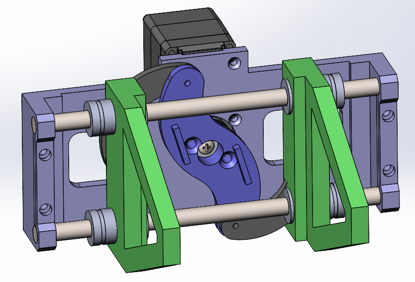
Rack and Pinion Gripper Mechanism
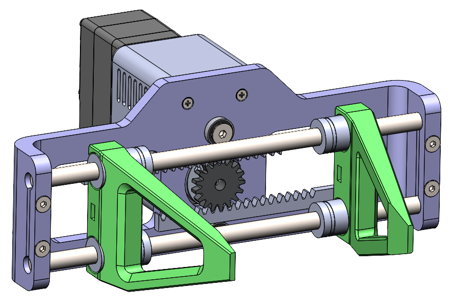
Rack and Pinion Gripper Mechanism. Version 1
In this image, we replaced the rocker arm with a rack mechanism. You can also see how much free space was gained compared to the previous version.
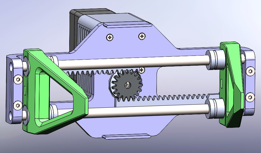
In the next stage, the engineer added stoppers and reduced the height of the assembly.
Rack and Pinion Gripper Mechanism. Version 2
One of the remaining drawbacks of the current design is the so-called “ears” — when the arm needs to reach into relatively narrow spaces, these extensions can significantly limit the ability to maneuver. This can also become a problem when working near flat surfaces if the gripper needs to rotate along its axis.
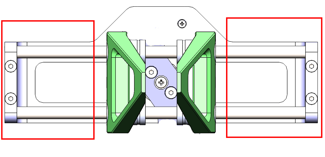
Gripper’s ears
Depth Camera
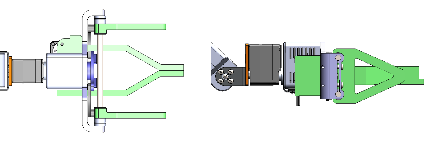
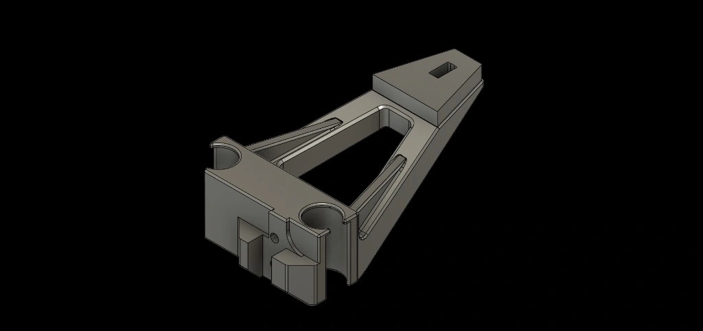
The gripper is used in combination with a depth camera, and at the next stage, a mounting plate was added for attaching the camera.
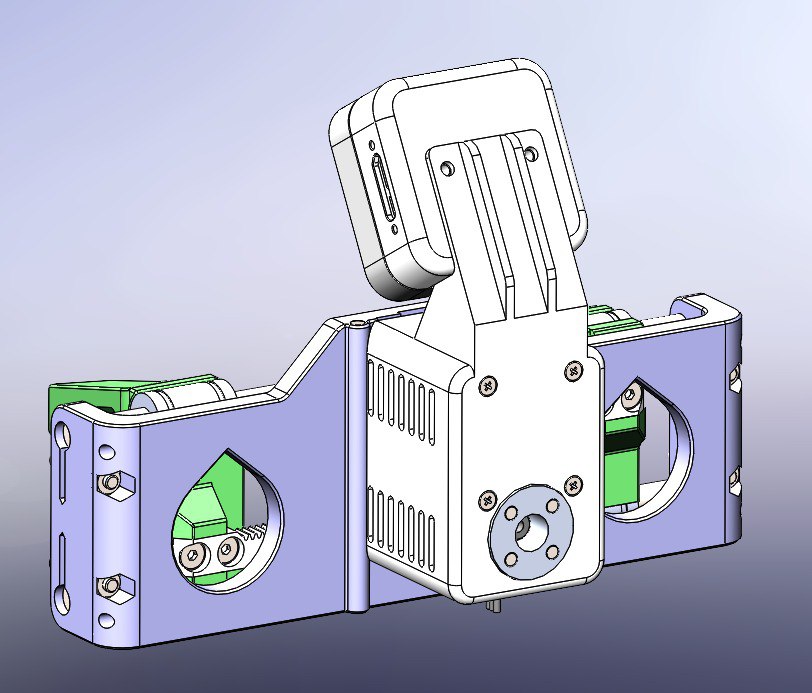
Depth camera mount
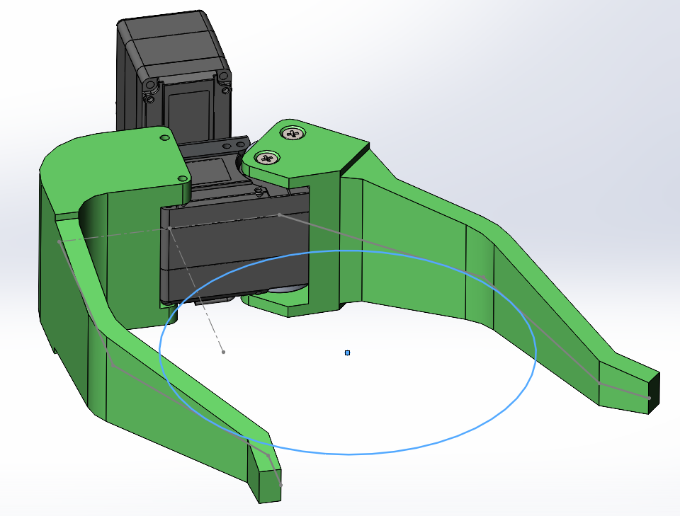
The camera is positioned at a 45-degree angle to achieve the widest possible working field of view. It is used by a machine learning control model to accurately determine the dimensions of the object to be grasped, the required gripping force, and the necessary jaw width. It is the only sensor installed on the gripper.
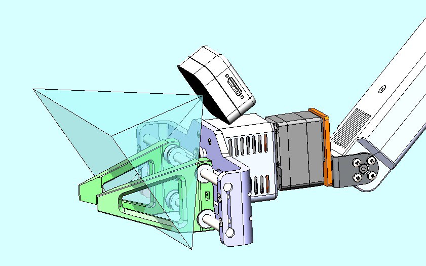
Depth camera angle of view
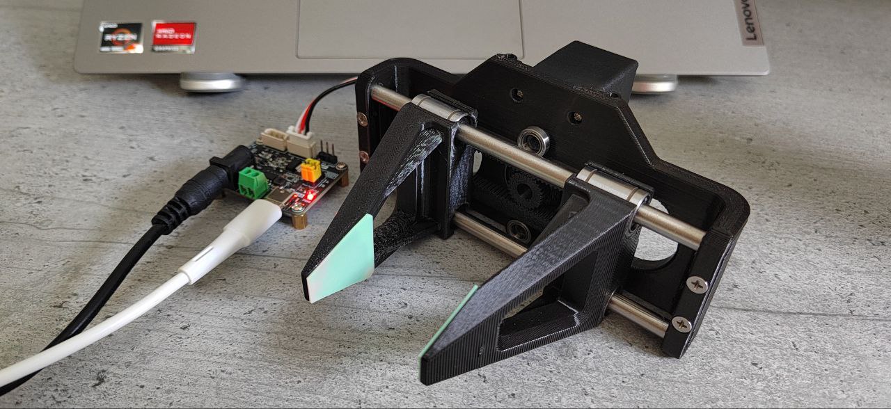
At this point, we’ve paused further design work and moved on to assembling the prototype to identify any practical issues with the current design. Some of the components were ordered from AliExpress.
Bill of Materials
Electronic Components
| Item | Description | Qty | Supplier Link | Price | Notes |
| ST3215 Servo | Waveshare Servo Motor STS3215 | 1 | Amazon – Waveshare STS3215 Servo | $28.99 | High-precision bus servo with feedback |
| Bus Servo Adapter | Waveshare Bus Servo Adapter Board | 1 | Amazon – Bus Servo Adapter A | $10.99 | TTL/RS485 communication interface |
Mechanical Components
| Item | Description | Qty | Supplier Link | Price | Notes |
| MR106ZZ | Ball Bearing 10×6×3 mm | 2 | Amazon – ACROPIX MR106ZZ Bearings (10pcs) | $5.49 (10pcs) | Shielded, pre-lubricated |
| LM6UU | Linear Bearing 6×12×19 mm | 4 | Amazon – uxcell LM6UU Bearings (4pcs) | $8.99 (4pcs) | For smooth linear motion |
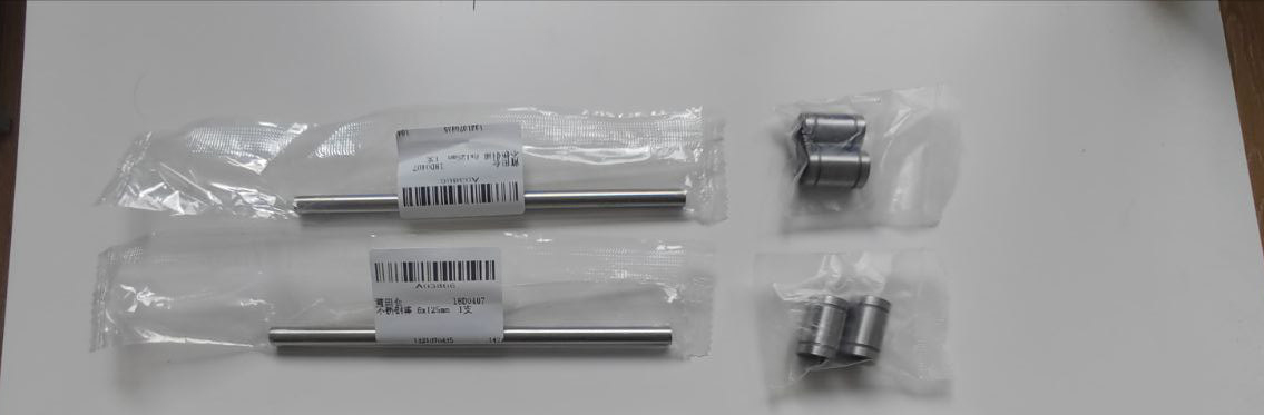
Steel rods and linear bearings
Rods
| Item | Description | Qty | Supplier Link | Price | Notes |
| Steel Rod | Stainless Steel Rod 6mm × 150mm | 2 | Amazon – uxcell Stainless Steel Rod 6mm×150mm (5pcs) | $8.39 (5pcs) | High precision, corrosion resistant |
3D-Printed Parts
| Part Number | Description | Qty | Material | Print Settings |
| RB9.01.060.010 | Main Frame | 1 | PLA/PETG | 0.2mm layer, 20% infill |
| RB9.01.060.020 | Clamp | 2 | PLA/PETG | 0.2mm layer, 20% infill |
| RB9.01.060.030 | Gear Rack | 2 | PLA/PETG | 0.15mm layer, 30% infill |
| RB9.01.060.040 | Drive Gear | 1 | PLA/PETG | 0.15mm layer, 30% infill |
3D Printing Notes
- Material: PLA recommended for prototyping, PETG for production use
- Layer Height: 0.15-0.2mm for optimal surface finish
- Infill: Higher infill (30%) recommended for gears to ensure strength
- Support: May be required depending on printer orientation
- Post-processing: Light sanding may be needed for bearing fits
Screws
| Item | Description | Qty | Standard | Price | Notes |
| M3×10 | Countersunk Screw | 4 | Amazon – M3×10 Countersunk Screws | $6.39 (100pcs) | For gear rack attachment |
| M3×20 | Countersunk Screw | 4 | Amazon – M3×20 Countersunk Screws | $6.99 (100pcs) | For clamp to rod attachment |
| M4×8 | Countersunk Screw | 2 | Amazon – M4×8 Countersunk Screws | $9.99 (100pcs) | For main frame bearing retention |
Nuts
| Item | Description | Qty | Standard | Price | Notes |
| M3 | Hex Nut | 4 | Amazon – M3 Hex Nuts | $5.99 (100pcs) | For clamp assembly |
Servo Hardware
| Item | Description | Qty | Source | Price | Notes |
| Self-tapping Screws | Servo mounting screws | 4 | Servo kit | Included | Included with STS3215 |
| Servo Disk | Output shaft adapter | 1 | Servo kit | Included | Included with STS3215 |
| Mounting Screw | Disk retention screw | 1 | Servo kit | Included | Included with STS3215 |
Cost Estimate
| Category | Estimated Cost (USD) |
| Electronic Components | $39.98 |
| Mechanical Components | $22.87 |
| 3D Printing Materials | $5-10 |
| Fasteners | $1.60 (approximate) |
| Total | $69.45-74.45 |
Costs based on Amazon pricing as of current date – 6th of June 2025. Bulk quantities provide significant savings on fasteners.
Assembly
Assembly guide:
https://github.com/roboninecom/3D-Printed-Parallel-Gripper-for-Robotics-Arms/blob/main/docs/assembly-guide.md
During the assembly of the first version, there was an issue with printing one of the gripper’s jaws, so the first test was conducted with only one jaw.
A few days later, the second jaw arrived, and we were able to carry out full testing.
The engineer added silicone pads for better grip on objects. This same first version has been published as open source on our GitHub:
https://github.com/roboninecom/3D-Printed-Parallel-Gripper-for-Robotics-Arms
Community Feedback
Hadassah Freedman:
“I was wondering if you’ve considered how the design handles heavier loads, especially around the base of the gear rack and jaw pivots. Possibly adding fillets in those areas to help reduce stress concentrations and avoid layer-splitting with FDM prints would help the design carry heavier loads over longer periods and more often. I see that the gear rack base has decent thickness but no clear fillets at the transition to vertical gear teeth, which can be a stress riser, and the jaw pivots have no visible filleting to smooth out load paths from the pivot pins into the sidewalls either. I would be curious to hear more about its capabilities.”
Joy Kariya:
“I went through the repository and I have a suggestion: why don’t you integrate limit switches on both sides of the gripper so that rather than being a time delay it will cut off when the object got gripped. So that it can grab small objects also.”
Gripper with Integrated limit switches
the linkage geometry reminds me of the old robotiq design, in a good way
that compliant fingertip design is clever
I want to make a slightly contrarian point about the whole rigid-linkage approach here, because while the repeatability argument is sound, I think for most hobbyist and research use cases the adaptability of an underactuated tendon gripper outweighs the consistency you gain. Real-world objects are messy, they’re not all the same size, and a gripper that conforms to whatever it’s holding will succeed on a far wider range of grasps than one that closes to a fixed geometry. Yes you give up some repeatability, but if your downstream task is ‘pick up this random thing on the table’ rather than ‘place this peg in this hole to 0.1mm,’ compliance wins. I’d love to see the design offered in both flavors.
does the gripper give any force feedback or is it purely position controlled off the servo?
It’s position-controlled, but the STS3215 reports motor current, so you can estimate grip force from current draw without adding a load cell. It’s coarse but usable for soft-grip logic.
Makes sense, thank you.
Worth noting for anyone printing this: orientation matters a lot. I printed the fingers flat the first time and they delaminated along the layer lines under load. Standing them up so the load runs along the print direction made them dramatically stronger.
are the print tolerances tight enough that this works straight off a bambu or do i need to tune fits?
On a well-calibrated Bambu it assembles with no tuning. On most printers you’ll want to check the pin-joint clearance — we left 0.2 mm, which is forgiving but not universal.
Appreciate the detailed answer.
clean. functional. open. exactly what the space needs.
Really like that you kept the part count low. Every extra fastener in a gripper is one more thing that loosens up after a few hundred cycles. The two-screw finger mount here is smart.
STL files when?? 🙏
how much grip force can this actually output with the STS3215 driving it?
It depends on the linkage ratio you choose — the STS3215 delivers 30 kg·cm of stall torque, and the design lets you trade speed for fingertip force by changing one link length. Pick the ratio for the grip force your task needs.
the parallel jaw kinematics look clean, well done
honestly the cleanest open gripper ive seen, finally something i can actually fork and modify without reverse engineering everything
printed this over the weekend and it came together really well, only change i made was reinforcing the base mount because the stock one flexed a bit when i cranked up the grip force. otherwise excellent design thank you for open sourcing it
I built basically this exact mechanism last year for a class project and the single hardest part was getting the finger pads to actually grip without slipping, ended up casting silicone pads in a 3d printed mold and that solved everything, highly recommend going that route if you’re fighting slip
printed mine in PETG and the hinges snapped on day two, going to try nylon next
what infill did you use for the finger links? worried about them flexing under grip force
We ran 40% gyroid infill on the finger links in PETG. That held the grip force fine; below 30% we did start to see flex at the base of each finger.
Perfect, exactly what I needed.
what cad package did you use for this? would like to open the source files natively rather than dealing with step imports
The native files are FreeCAD, and we also export STEP for everyone else. Both are in the repo so you can pick whichever fits your workflow.
underactuated grippers are SO underrated for general grasping imo
any reason you didnt use a worm drive to hold grip force without burning current?
A worm drive would hold force passively, yes, but it adds height and removes back-drivability, which matters for safe interaction. For this teaching gripper we accepted the holding current as a trade-off.
Whats the smallest object this can reliably pick? thinking surface-mount parts here
As designed, reliably down to about 5 mm. For SMD-scale parts you’d want narrower fingertips and probably a vacuum end-effector instead — parallel jaws struggle below a few millimetres.
the design is nice but i think youre underselling how much the servo backlash shows up at the fingertip, on a long finger link even a degree of slop becomes a couple mm of uncertainty at the tip
love seeing actuation, mechanics and print settings all in one post instead of having to dig through three different repos to figure out how the thing actually goes together
soo satisfying watching that close in the video, great work team!!
did you consider a tendon-driven design instead of the linkage? curious why you went rigid
We prototyped a tendon version first but the cable stretch and routing made it hard to keep consistent grip force. The rigid linkage was more repeatable for a teaching platform, which was our priority.
Built three iterations of grippers for our lab manipulator and the lesson that took me longest to learn is exactly what this post leads with: design for the actuator you have, not the one you wish you had. We kept speccing grippers around torque we couldn’t actually deliver at the joint and then wondering why they stalled on anything heavier than a marker. Sizing the linkage ratio to the real servo torque curve, with margin, is the whole game. Glad to see that called out so plainly here.
the thumb opposition angle feels a touch aggressive but thats easy to tweak in cad