How motion control works
A destination command does not directly set a fixed motor output. In Extension mode, the host supplies targets and limits; each servo plans a trajectory, measures movement and computes output. This page explains those relationships. Use the tuning guide for the practical sequence.
How extension mode works
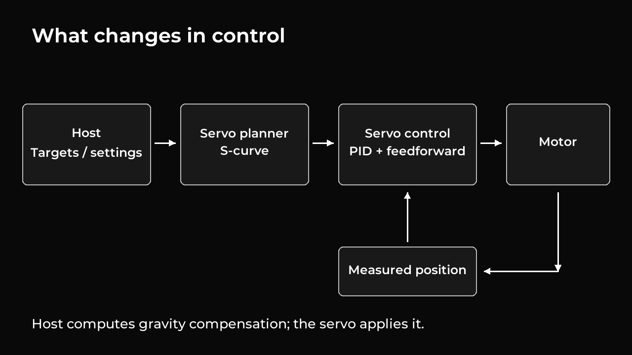
The host is the computer or controller connected to the servos. It sends a target: a destination and speed limit. Acceleration and compensation settings are configured before enabling motor power. Each servo then:
- Plans a smooth movement toward the destination.
- Measures its position and estimates its speed.
- Adjusts motor output to follow the planned movement.
- Holds the destination when the movement finishes.
The planned position and speed at any moment are called the reference. The controller compares them with the measured movement, so a reference position and an actual position can differ.
A few terms used throughout this document:
| Term | Meaning |
|---|---|
| Encoder count | A position measurement unit; nominally 4096 counts per revolution |
| Effort | The signed motor-output command: its sign sets direction and its size sets output strength |
| Gain | A setting that determines how strongly the controller responds |
| Feedforward | Extra motor output calculated from expected demand, rather than waiting for a position or speed error |
| Feedback | Measurements and status returned by the servo |
| Register | A setting or reading identified by a number |
| Session | One period of extension control, identified by a number supplied by the host |
Effort is expressed in PWM units, the units used to control electrical output to the motor. The extension allows an output limit up to 1000 in either direction. These values are not direct measurements of torque or current.
S-curve motion
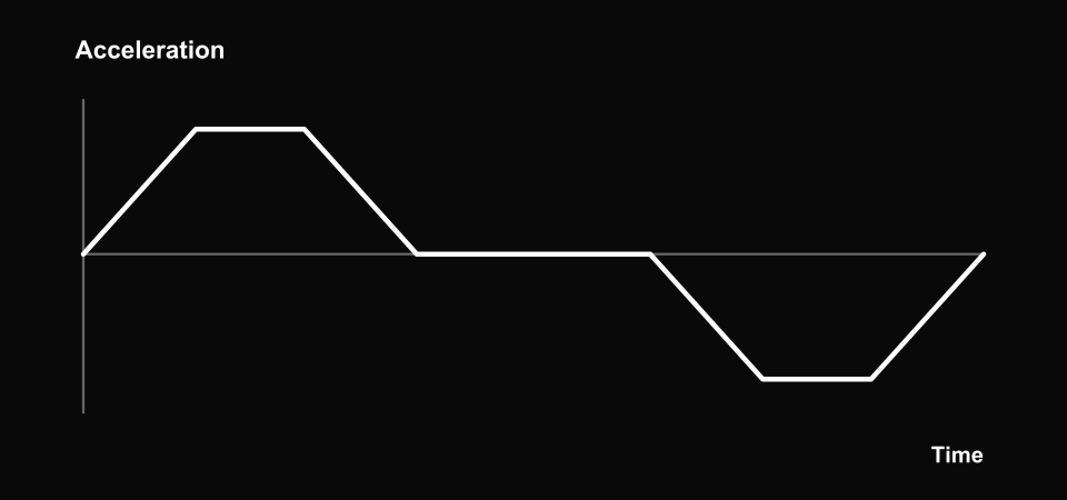
Makes acceleration and braking more gradual. The curve illustrates acceleration over time. Conceptual illustration, not measured hardware data.
An S-curve makes acceleration increase and decrease gradually. Instead of suddenly applying full acceleration or braking, the servo eases into and out of each part of the movement. This can reduce mechanical jolts and vibration.
A full movement from rest to rest has these stages:
| Stage | What happens |
|---|---|
| 1 | Acceleration gradually increases |
| 2 | The servo accelerates at a steady rate |
| 3 | Acceleration gradually decreases to zero |
| 4 | The servo moves at a steady speed |
| 5 | Braking gradually increases |
| 6 | The servo brakes at a steady rate |
| 7 | Braking gradually decreases as the servo stops |
Short moves skip stages when there is not enough distance to reach the requested speed or acceleration. The same acceleration limit applies when speeding up and slowing down.
The ramp_time_ms setting controls how long acceleration takes to rise from zero
to its limit. A longer ramp gives a gentler change, but generally needs more time
and distance to accelerate or stop.
Jerk means the rate at which acceleration changes. This planner limits jerk, so acceleration changes smoothly. Jerk itself can still change abruptly between stages. Its approximate magnitude is:
jerk = 1000 × acceleration / ramp_time_ms [counts/s³]
Changing a destination during movement
A new target continues from the current planned movement, preserving its position, speed, and acceleration. Sending the same destination again does not restart the move. Keep the same requested speed limit while moving; it can change for the next move once the planned movement has stopped. Acceleration and ramp time belong to configuration and require motor power off and a disarmed session to change.
A destination outside the saved legacy position limits is adjusted to the nearest limit. Requested speed is also capped at its configured limit. The servo uses the configured acceleration for every move. Zero speed or configured acceleration is invalid.
The whole planned movement must stay inside the position limits. A new target can therefore be rejected if the servo is already approaching a limit too fast to stop within it, even when the destination itself is allowed.
On arrival, the servo automatically holds the destination with motor power on. The measured position may still have some error due to friction, load, output limits, or tuning. Holding continues to correct position error; it does not freeze the motor output at a fixed value.
Each servo plans its own movement. Sending several targets together does not guarantee that all servos will arrive at the same time.
Shared position limits
Legacy and extension control use the same position-limit registers: 9–10 contain the minimum and 11–12 the maximum. Each is an unsigned 16-bit value in corrected encoder counts, including the servo’s configured direction and position correction. There are no separate extension position-limit settings.
Calibration assigns encoder counts to physical positions. The calibration tool makes the captured reference pose read 2048, then measures travel limits. That count is not automatically a zero-degree joint angle, and the measured travel midpoint does not replace the captured reference. Gravity models and visualizations need a matching count-to-angle mapping.
The firmware reads these registers when starting control. With limits enabled, the minimum must be below the maximum, the maximum must be at most 32767, and the measured position must be inside the range. Otherwise startup fails without moving the motor. The planner keeps the complete movement, including braking, within the range it read.
Equal minimum and maximum values disable the travel limits, matching legacy behavior. Extension commands still stay within their supported position range of −32767 to 32767 counts.
An accepted write to either limit ends an active extension session and turns motor power off, including writes that are only applied in RAM. Arm a new session to use the changed values. Normal legacy settings persistence still applies.
PID controller
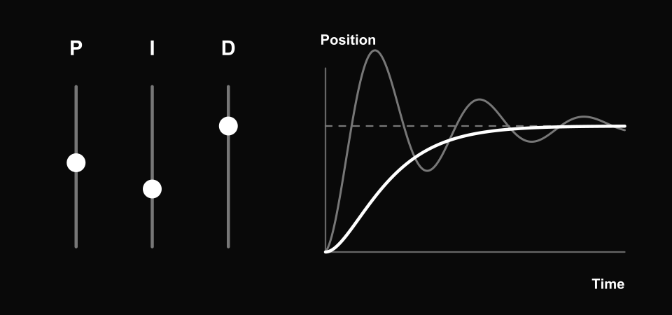
Adjusts how the servo corrects position error. The gray curve illustrates oscillation; the white curve illustrates a more damped response. The dashed line is the target. Conceptual illustration, not measured hardware data.
The PID controller adjusts motor output to follow the planned movement. Its three settings have different jobs:
| Setting | What it does | Main tradeoff |
|---|---|---|
| P — position correction | Pulls the motor toward the planned position; larger errors produce more correction | Higher P can reduce error but can also cause oscillation |
| I — accumulated correction | Builds up extra correction when an error persists | Can reduce a lasting error, but may increase overshoot or settling time |
| D — speed correction | Responds to the difference between planned and measured speed; resists movement while holding | Can improve damping, but excessive response to noisy speed readings can make output uneven |
The calculation is:
position error = planned position − measured position
speed error = planned speed − filtered measured speed

motor output = Kp × position error
             + Kd × speed error
             + accumulated I correction
             + gravity compensation
             + velocity feedforward
The result is limited to the configured maximum output. Motor protection can reduce it further. Feedback reports both the requested and applied output so the host can see when the motor is being limited.
Measured speed is smoothed using recent position readings and an adjustable
filter. A larger velocity_filter_q8 setting responds faster to changes but
removes less measurement noise.
Preventing excessive accumulated correction
The I contribution has its own limit. The controller also prevents it from
continuing to build in a direction where the motor output is already limited;
this is commonly called anti-windup. It can still decrease to help the motor
recover from that limit. Setting Ki to zero disables and clears I correction.
When the servo has been nearly stationary for at least 50 ms and the position error is within one encoder count, I stops accumulating. P, D, and both forms of feedforward remain active. Turning motor output off clears I correction.
Velocity feedforward
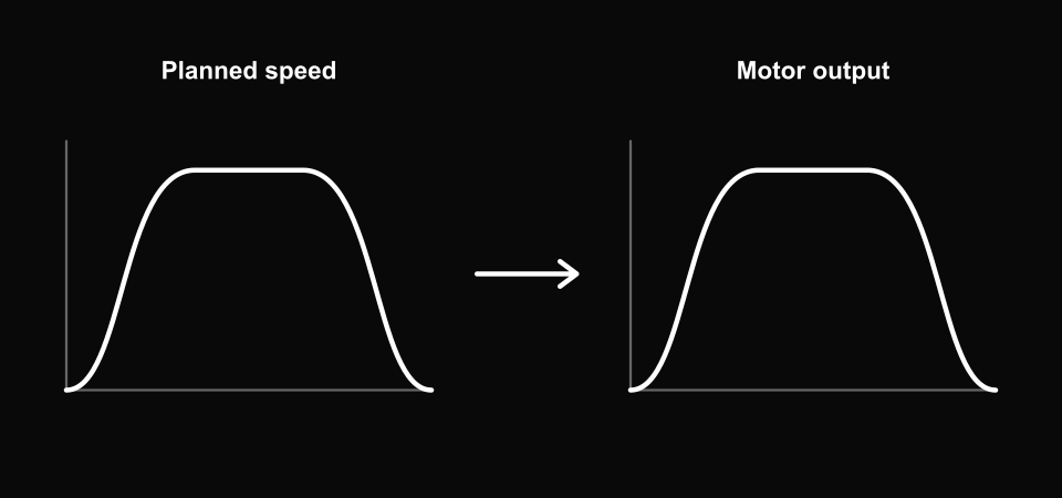
Adds motor output based on planned speed, calculated inside the servo. Both curves progress from left to right over time. Conceptual illustration, not measured hardware data.
Velocity feedforward supplies some of the output expected to be needed for movement before a tracking error develops. It is calculated inside the servo from the planned speed:
velocity feedforward = velocity gain × planned speed
There is one gain for each direction and a limit on the resulting output. Both gains are nonnegative; movement direction determines the output sign. Its output limit must be no greater than the main motor-output limit.
Because the servo knows its own planned speed, the compensation follows acceleration and braking automatically and becomes zero when the planned motion stops. The host only supplies its settings; it does not need to send continuous velocity-feedforward values.
Configure this feature together with the other settings in 0xA0, while motor
power is off and the session is disarmed. Set both gains and its output limit
to zero to disable it.
Gravity compensation
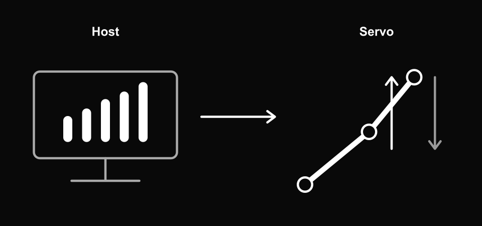
The host calculates the contribution and the servo applies it. The downward arrow represents weight; the upward arrow represents support. Conceptual illustration, not measured hardware data.
Gravity compensation provides the output needed to support the weight of an arm and its load. It is useful even when the motor is holding still, where velocity feedforward is zero.
The host calculates gravity compensation and sends a signed output value to each servo. The calculation can use joint angles, arm dimensions, link weights, and payload. The host must convert the estimated load into the servo’s output units. The firmware does not contain a model of the arm.
Direction matters: positive extension output follows increasing encoder counts. An arm’s joint-angle convention may run in the opposite direction, so the host’s conversion must account for that.
Each gravity update contains the desired output value. The slew rate—how quickly compensation may change, in output units per second—is part of the main configuration and remains fixed throughout the session.
The servo gradually changes its compensation toward the requested value and adds it to the controller output. All contributions together remain subject to the configured output limit and motor protection.
If gravity updates stop arriving, the servo continues toward the last requested compensation at its configured slew rate, then keeps that value. There is no expiry timer. The host should update compensation when the arm pose or load changes. Setting torque-enable register 40 to zero clears compensation and turns motor output off.
Apply the explanation to tuning
If a short move never reaches its requested speed, raising the speed limit may not make it faster. Prolonged output saturation calls for checking load, trajectory and permitted effort, not only higher gains. If the encoder follows its reference but the tool misses a physical point, check calibration, geometry and mechanics.
Distinguish planned and measured movement, and positioning accuracy and repeatability. The four control diagrams and animations above are conceptual rather than measured servo plots.
Documentation home · Source revision: a995f77. Extension 9.0.