Practical Comparison of Smart Serial Servo Motors for Robotics
 41
41
Smart serial servos have become a common choice for affordable DIY robotics projects, including robotic arms, robotic dogs, and similar compact mechanisms. They combine a motor, gearbox, encoder, controller, and serial interface in one package, which makes them much easier to integrate than a bare motor and external driver.
There are quite a few models available, but datasheets do not always answer the questions that matter once the servo is installed in a real mechanism. Published torque, speed, and current ratings are useful starting points, yet they do not fully describe power consumption, temperature rise under load, behavior near rated torque, or how long the servo can hold constant torque without overheating or shutting down.
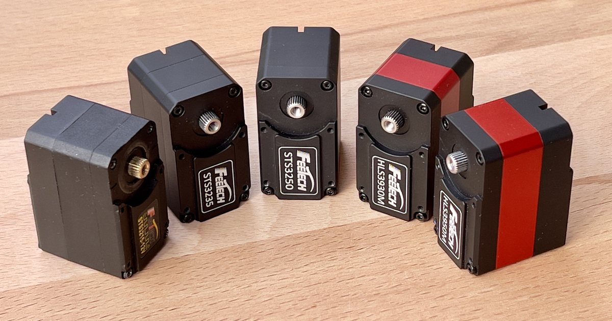
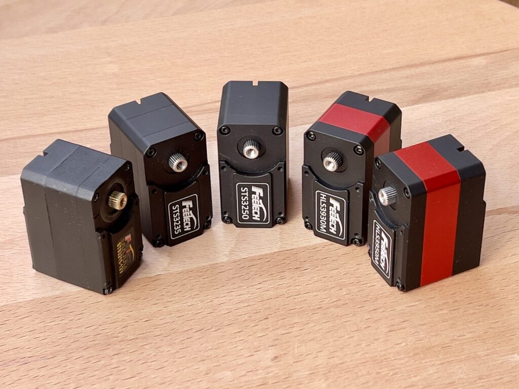
For this comparison, we tested five popular models that cover both lower-cost and more capable options:
The goal is to evaluate practical tradeoffs: maximum torque, current consumption, temperature rise under load, rated-torque behavior, backlash, and construction details such as brass versus all-steel gears and plastic versus metal cases. We also pay special attention to constant-force operation, because manufacturer documentation does not provide enough detail to judge that behavior from the datasheet alone.
Specifications compared
The main common point is that all five servos are built around the same control idea: a TTL serial smart servo with a dual-shaft output, magnetic encoder feedback, digital packet control, and an internal PID loop. They also share the same 1/345 gear ratio, the same claimed backlash limit of 0.5 degrees or less, the same 25T horn format, and almost the same physical envelope. That means they can usually be considered mechanically similar when planning a robot joint, at least from the outside.
The biggest differences are in torque class, construction, speed, and motor type. STS3215 and STS3235 are the lower 30 kg·cm class options, HLS3930M sits in the middle at 35 kg·cm, and STS3250 and HLS3950M are the 50 kg·cm class options. The faster models are STS3250 and HLS3950M, both listed at 75 RPM, while the others are listed at 45 RPM. The 50 kg·cm models also use coreless motors, which makes them more interesting for applications that need higher speed and stronger response.
Construction is another practical split. STS3215 is the lightest servo and the only one in this group with a PA+GF plastic case. It also lists copper / metal gearing rather than all-steel gears. The other four servos use aluminum cases and steel gears, so they should be better candidates for higher-load joints, harsher duty cycles, and situations where gearbox durability matters more than saving a few grams.
The current ratings also show that higher torque does not translate into a simple linear increase in listed current. STS3250 has the highest listed stall current at 4.2 A, while HLS3950M is listed at 2.4 A despite being in the same 50 kg·cm torque class. That difference is one reason bench testing is important: the datasheet numbers suggest the motors are not just scaled versions of one another, and real current consumption under load needs to be measured directly.
The manufacturer specifications below are useful for narrowing the field before testing.
Model-specific specifications
| Spec | STS3215 | STS3235 | STS3250 | HLS3930M | HLS3950M |
|---|---|---|---|---|---|
| Weight | 55 ±1 g | 70.5 ±1 g | 74.5 ±1 g | 70.5 ±1 g | 74.5 ±1 g |
| Max torque / stall torque | 30 kg·cm | 30 kg·cm | 50 kg·cm | 35 kg·cm | 50 kg·cm |
| Rated torque | 10 kg·cm | 10 kg·cm | 16 kg·cm | 8.7 kg·cm | 12.5 kg·cm |
| Max current / stall current | 2.7 A | 2.7 A | 4.2 A | 2.8 A | 2.4 A |
| Rated current | 900 mA | 900 mA | 1400 mA | 800 mA | 600 mA |
| Gear material | Copper / metal gear | Steel gear | Steel gear | Steel gear | Steel gear |
| Case material | PA+GF plastic | Aluminium | Aluminium | Aluminium | Aluminium |
| Max RPM / no-load speed | 45 RPM | 45 RPM | 75 RPM | 45 RPM | 75 RPM |
| Motor type | Core motor | Core motor | Coreless motor | Core motor | Coreless motor |
Common specifications
| Spec | Common value |
|---|---|
| Size | 45.22 × 24.72 × 35 mm |
| Type | TTL serial servo, dual-shaft, magnetic encoder |
| Encoder resolution | 12-bit magnetic encoder; 4096 encoder counts, 0.088° per pulse |
| Control type | Digital packet, half-duplex asynchronous serial; PID control |
| Horn type | 25T / OD 5.9 mm |
| Gear ratio | 1/345 |
| Backlash | ≤0.5° |
| Protections | Overload, over-voltage, over-temperature, over-current |
Constant-force servos and force feedback
For this article, a constant-force servo means a smart servo that can be used as a controlled-force actuator, not only as a position actuator. In a small serial servo this usually does not mean laboratory-grade force control with a calibrated load cell. It means the controller can command or limit motor effort, usually through current or torque-related parameters, and the mechanism can react against the load instead of simply driving toward a target angle at full available force.
The STS-series motors are mainly position servos with torque limiting. They can reduce output through the Torque Limit setting, which helps protect mechanisms, but the control model is still centered around position commands. The HLS-series servos are more interesting for force-sensitive applications because torque can be entered directly as part of the motion command, and the current sensing appears to be much more sensitive. That makes small changes in load easier to observe and use in software.
This behavior is useful in grippers, where the goal is often to close until contact and then keep applying a controlled holding force instead of crushing the object. It is also useful in leader arms and teaching handles, where a person moves the mechanism by hand and the controller reads position, load, or resistance as feedback. In that role, the servo is not just moving a joint; it becomes part of the input device.
Other practical examples include exoskeleton joints, assistive braces, haptic knobs, teleoperation handles, robot hands, cable-tensioning mechanisms, compliant robot arms, end-effector contact detection, spring-loaded test fixtures, and safety-limited educational robots. In these cases, predictable force behavior and readable current feedback can matter more than the highest possible stall torque.
The tradeoff is heat. A constant-force application can keep the motor energized even when the output shaft is barely moving, so electrical power turns into heat during holding. That is why current draw, temperature rise, and case material are central to this comparison: force-control behavior is only useful if the motor, driver, gearbox, and case can survive the intended duty cycle.
Test setup and methods
Each servo was evaluated with three practical bench tests: a short maximum torque and maximum current test, a two-minute temperature rise test under 50% load, and a backlash measurement while the servo held position. Together, these tests cover peak output, sustained-load thermal behavior, current demand, and mechanical play at the output.
Maximum torque and current test
The maximum torque test used a 3D-printed frame to hold a digital hanging scale rigidly in front of the servo. A 10 cm lever arm was attached to the servo horn and set perpendicular to the scale. In the neutral position, the lever was connected to the scale without preloading it.
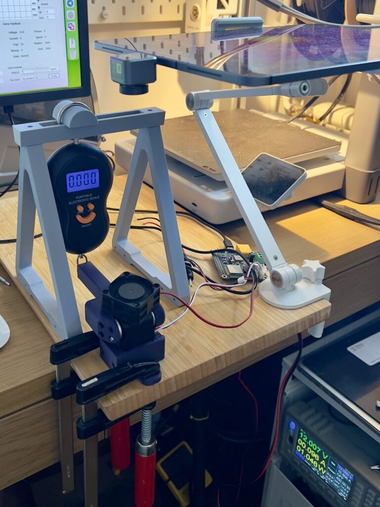
A scripted sequence of movements drove the servo against the scale and loaded it toward the maximum torque the motor could produce. Because the lever arm was 10 cm long, the scale reading can be converted directly into torque: torque in kg·cm is the scale reading in kgf multiplied by 10. The same result can be expressed in Nm as kgf × 0.9807.
This test represents a short peak-torque condition, not a normal operating point. It is useful as a reference for comparing how much force each servo can produce before it stalls, saturates, or reaches a practical current limit. It should not be confused with rated torque: rated torque is the load a servo is expected to handle more continuously, while maximum or stall torque is a short-duration limit and is much higher than the rated value. For example, a servo rated for 10 kg·cm may advertise 30 kg·cm stall torque, but that does not mean it can safely hold 30 kg·cm as a continuous joint load.
All motors were powered through a Waveshare Servo Motor Driver HAT board capable of handling 10 A loads. The bench power supply was configured for 12 V with a 10 A current limit. During each test sequence, we recorded both the servo logs and video, so the measured torque and current can be checked against the visible behavior of the stand.
Temperature rise test under 50% load
The second test measured temperature rise while the servo held approximately 50% load for two minutes. This test is closer to a practical continuous-load scenario than the maximum torque test, because many robot joints spend more time holding or resisting load than briefly hitting stall torque.
During this test, we collected temperature data from two sources: the servo’s internal temperature sensor and an external thermal camera. The internal sensor shows what the servo reports through its telemetry, while the thermal camera gives an independent view of case and surface heating. Comparing both readings helps identify whether heat is concentrated inside the motor/driver or spreading through the case.
This test represents thermal behavior under sustained partial load. It helps answer a more practical question than peak torque alone: whether the servo can hold a meaningful load for a short working period without excessive heating, current draw, or signs of thermal stress.
Backlash measurement test
The third test measured backlash while the servo was actively holding its commanded position. A 10 cm lever was mechanically stressed in two directions, creating small oscillations around the held position without commanding the motor to move. During this process, log data containing encoder position error were recorded.
Backlash was calculated from the spread between the minimum and maximum position error observed during the test. To reduce the effect of noise and single-sample spikes, the calculation used averaged values from a few oscillations in each direction rather than only one raw minimum and one raw maximum.
The final backlash value was converted from encoder counts to degrees using the encoder resolution. With the 12-bit magnetic encoder, one count is approximately 0.088°, so backlash in degrees is calculated as position error counts × 0.088°. This test represents how much mechanical play appears at the output when the servo is trying to hold a fixed position against small external forces.
Test results
Torque and current
The first result set compares short peak-load behavior against the 50% load point used for the thermal test. Scale readings are shown as kgf because they come directly from the hanging scale. With the 10 cm lever, torque in kg·cm is scale reading × 10.
The load control was different between the two servo families. For the STS-series motors, output torque was limited through the Torque Limit setting. For the HLS-series motors, the current value was entered directly as a motion command parameter.
| Motor | Load | Scale reading (kgf) | Torque (kg·cm) | Current (A) |
|---|---|---|---|---|
| STS3215 | 100% load | 3.3 | 33.0 | 2.8 |
| STS3215 | 50% load | 2.2 | 22.0 | 0.75 |
| STS3235 | 100% load | 3.0 | 30.0 | 2.4 |
| STS3235 | 50% load | 2.2 | 22.0 | 0.75 |
| STS3250 | 100% load | 5.2 | 52.0 | 4.7 |
| STS3250 | 50% load | 3.5 | 35.0 | 1.6 |
| HLS3930M | 100% load | 2.8 | 28.0 | 2.4 |
| HLS3930M | 50% load | 2.2 | 22.0 | 0.75 |
| HLS3950M | 100% load | 6.3 | 63.0 | 6.0 |
| HLS3950M | 50% load | 3.5 | 35.0 | 2.4 |
HLS3950M produced the highest measured peak torque at 63.0 kg·cm, but it also drew the highest peak current at 6.0 A. It is the strongest motor in this test set, but it needs the most electrical and thermal headroom.
STS3250 also produced strong torque at 52.0 kg·cm and reached 35.0 kg·cm at the 50% test point.
One of the clearest observations is that current consumption follows the actual load level more than the servo model name. At the similar 22.0 kg·cm load point, STS3215, STS3235, and HLS3930M all drew about 0.75 A. At the higher 35.0 kg·cm load point, STS3250 and HLS3950M moved into a higher current range. In practice, this means servos from different families can consume very similar current when they are doing similar mechanical work. This also means the HLS-series motors did not appear to be more efficient in these measurements, despite the more favorable datasheet current values. At comparable mechanical load, their current draw was in the same practical range as the STS-series motors.
During repeated 100% load test attempts, two motors were damaged despite temperature control and cooling. The STS3215 failed with a burnt controller board, while the STS3250 failed with a burnt motor. This is an important practical result: maximum torque testing should be treated as a short reference measurement, not as a safe continuous operating mode.
Torque test recordings
Temperature rise results
The temperature test was run at the 50% load point. The table below combines internal servo temperature telemetry with the thermal-camera readings captured during the same style of test.
| Motor | Internal start (°C) | Internal end (°C) | Internal delta (°C) | Camera start (°C) | Camera end (°C) | Camera delta (°C) |
|---|---|---|---|---|---|---|
| STS3215 | 31.0 | 41.0 | 10.0 | 30.0 | 33.5 | 3.5 |
| STS3235 | 31.0 | 36.0 | 5.0 | 30.0 | 34.5 | 4.5 |
| STS3250 | 30.0 | 55.0 | 25.0 | 30.0 | 54.0 | 24.0 |
| HLS3930M | 33.0 | 35.0 | 2.0 | 30.0 | 31.7 | 1.7 |
| HLS3950M | 31.0 | 39.0 | 8.0 | 30.0 | 35.6 | 5.6 |
STS3250 was the clear thermal outlier in this test. Its internal telemetry rose from 30 °C to 55 °C, and the thermal camera showed a very similar surface rise from 30 °C to 54 °C. That is much higher than the rest of the group under the same 50% load test condition.
HLS3930M showed the smallest rise in the captured data, with internal telemetry increasing by only 2 °C and thermal-camera temperature by 1.7 °C.
STS3215 is important for a different reason: its internal temperature rose by 10 °C, while the external thermal-camera reading rose only 3.5 °C. The thermal image shows heat concentrated inside the body. With the plastic PA+GF case, heat dissipation is much worse than on the aluminum-case servos, so the outside case temperature can understate the internal heating risk during sustained holding.
Overall, the temperature data supports the current measurements: similar mechanical load produces similar electrical and thermal stress across several models, while case construction strongly affects how that heat escapes. For compact robot joints that hold load for long periods, temperature margin and case material are just as important as the headline torque number.
Temperature test recordings
Backlash test results
Backlash was calculated from selected positive and negative encoder-error plateaus while each servo held position.
| Motor | Positive avg (counts) | Negative avg (counts) | Backlash (counts) | Backlash (deg) |
|---|---|---|---|---|
| STS3215 | 3.75 | -5.00 | 8.75 | 0.769 |
| STS3235 | 4.00 | -1.00 | 5.00 | 0.439 |
| STS3250 | 1.50 | -1.67 | 3.17 | 0.278 |
| HLS3930M | 2.00 | -2.00 | 4.00 | 0.352 |
| HLS3950M | 3.20 | -3.25 | 6.45 | 0.567 |
STS3250 had the lowest measured backlash in this test at 0.278 degrees, followed by HLS3930M at 0.352 degrees and STS3235 at 0.439 degrees. These three stayed below the 0.5 degree specification limit.
STS3215 showed the largest measured backlash at 0.769 degrees, clearly above the stated 0.5 degree limit. HLS3950M was also above the limit at 0.567 degrees.
The result does not map directly to torque class. The strongest servo in the torque test, HLS3950M, did not have the best backlash result, while STS3250 measured best in this set. For joints where positioning feel matters, gearbox behavior should be checked directly rather than inferred from maximum torque alone.
Conclusions
The tests confirmed most of the published specifications, but they also showed why datasheets are not enough when selecting servos for a robot. Some values were difficult to rely on before testing. Backlash is one example: several motors were close to the claimed limit, but STS3215 and HLS3950M measured worse than the 0.5 degree specification. Current is another example: the datasheet values suggested large efficiency differences, but at similar mechanical load the motors often consumed about the same current.
STS3215 is the most basic motor in this comparison. It is light and inexpensive, but it also has the clearest limitations: plastic case, weaker heat dissipation, temperature concerns under sustained load, and the worst measured backlash. It is still useful for simple low-cost applications, especially where high constant force is not required. It can also be a good fit for leader arms, teaching rigs, and other manually moved mechanisms where low cost and easy integration matter more than maximum output power.
STS3235 looks like a stronger practical option than STS3215 while staying in a similar torque class. The headline torque and speed specs are close, but STS3235 has steel gears, an aluminum case, and better measured backlash. For many compact robot joints, it is likely the safer choice when the STS3215 envelope is attractive but the plastic case and gearbox behavior are concerns.
STS3250 is one of the strongest candidates in the group. It has high torque, high RPM, an all-metal construction, and the best measured backlash in our test. Those are strong advantages for robot joints that need both force and positioning feel. The main caution is thermal behavior: we observed an unusual temperature rise during the 50% load test. That could be related to the specific test condition or to this particular motor sample, so it should be retested before drawing a broad conclusion about the model.
HLS3930M is an interesting option, but in these measurements it appeared a bit weaker than the others. Its peak torque result was lower than the comparable STS options, and it is not the obvious choice if the only goal is maximum output. Its advantage is the HLS control behavior: direct torque command and more sensitive current feedback make it useful for grippers, leader arms, force-feedback experiments, and mechanisms where detecting contact or load changes matters.
HLS3950M produced the highest measured peak torque, so it is the strongest motor in this test set. However, the backlash result was disappointing, and it also requires serious electrical headroom at high load. It is a good candidate when maximum force is the main priority, but it is less convincing for precision joints where output play is important.
Overall, the best choice depends on the application. For cheap and simple mechanisms, STS3215 can be enough. For a more robust low-cost joint, STS3235 is more attractive. For high torque with good measured backlash, STS3250 is the strongest candidate, provided thermal behavior is validated. For force-sensitive applications such as grippers and leader arms, the HLS-series control behavior may be more valuable than raw efficiency. For maximum torque, HLS3950M leads, but its backlash should be considered carefully.
Log in to leave a comment.