Extension register layouts
Block reference for protocol v9.0. Offsets start at the beginning of each block; they are not separate Legacy register addresses. Read each complete block at its exact length. See packet format and startup order separately.
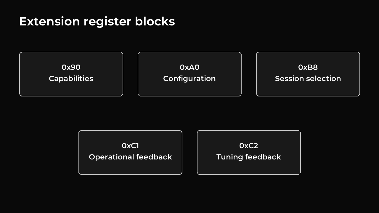
An offset is the starting byte of a field, counting from zero within its
block. Offsets below are decimal; selectors use hexadecimal notation (0x...). All writes use instruction 0x91; reads use
0x90 with the exact byte count.
| Selector | Block | Access | Bytes |
|---|---|---|---|
0x90 |
Capabilities | Read | 8 |
0xA0 |
Configuration | Read/write | 24 |
0xB8 |
Controller selection and session setup | Write | 3 |
0xC1 |
Operational feedback | Read | 32 |
0xC2 |
Tuning feedback | Read | 54 |
Capabilities — 0x90
| Offset | Type | Value / meaning |
|---|---|---|
| 0–3 | 4 bytes | ASCII ARMC |
| 4 | u8 |
Major version: 9 |
| 5 | u8 |
Minor version: 0 |
| 6 | u8 |
Reserved: 0 |
| 7 | u8 |
Normal controller update interval: 1 ms |
The protocol version defines the available blocks and their exact lengths. Selection and session setup share one write-only block, documented below.
Configuration — 0xA0
| Offset | Type | Field | Units / valid range |
|---|---|---|---|
| 0 | u16 |
kp_q8 |
Gain × 256; 0–65535 |
| 2 | u16 |
kd_q8 |
Gain × 256; 0–65535 |
| 4 | u16 |
ki_q8 |
Gain × 256; 0–65535 |
| 6 | u16 |
integral_limit |
Effort; 0–effort_limit |
| 8 | u16 |
effort_limit |
Effort; 1–1000 |
| 10 | u16 |
velocity_limit |
Counts/s; 1–65535 |
| 12 | u16 |
acceleration_limit |
Counts/s²; 1–30000 |
| 14 | u8 |
velocity_filter_q8 |
Speed-filter response; 1–255, higher responds faster |
| 15 | u8 |
ramp_time_ms |
Acceleration ramp; 1–255 ms |
| 16 | u16 |
velocity_ff.positive_gain_q8 |
Output/(count/s) × 256; 0–65535 |
| 18 | u16 |
velocity_ff.negative_gain_q8 |
Output/(count/s) × 256; 0–65535 |
| 20 | u16 |
velocity_ff.effort_limit |
Effort; 0–main effort_limit |
| 22 | u16 |
gravity_slew |
Compensation change, effort units/s; 1–10000 |
Gains are sent as the desired value multiplied by 256. Their units are output/count for P, output/(count/s) for D, and output/(count·s) for I. For example, P = 4.5 produces 4.5 output units per count of error and is sent as 1152.
The servo has one active configuration. Writing it requires motor power off and a disarmed session.
Every write replaces the entire configuration, including feedforward
settings. Invalid settings reject the entire write without changing anything.
Read 0xA0 to check the settings that were accepted.
Velocity-feedforward gains are nonnegative. A zero feedforward output limit requires both gains to be zero. The same feedforward output limit applies in both directions and must not exceed the main output limit.
After a reset, configure the servo before enabling motor power. Keep saved settings and alternative tuning values on the host; change gains between runs with the arm supported and motor power off.
Selection and session setup — 0xB8
| Offset | Type | Meaning |
|---|---|---|
| 0 | u8 |
Mode: 0 legacy, 1 extension |
| 1 | u16 |
Session: 0 for legacy, 1–65535 for extension |
The exact payload length is 3 bytes, with the session in little-endian order.
For example, extension mode with session 0x1234 is 01 34 12; legacy mode is
00 00 00. Invalid combinations reject the whole write without changing state.
Both modes require motor power off and replace any earlier session setup.
Selection alone does not start control or capture a holding position.
Legacy torque-enable register 40 starts the prepared extension session when
written to 1. It requires available motor output, a valid configuration, initialized sensors with
readings no more than 2 ms old, no fault requiring shutdown, and usable saved
legacy position limits. The measured position must be within those limits when
they are enabled. These checks happen at enable time, so movement or faults
between setup and enable are taken into account.
Torque-off cancels both running control and unused setup. Sensor failures,
protection shutdown, position-limit or encoder-offset changes, calibration and
saving permanent settings also invalidate session setup. Read feedback to check
whether control has actually started; there is no separate ARM command.
The former 0xBA selector and former one-byte selection payload are rejected.
Operational feedback — 0xC1
| Offset | Type | Field / units |
|---|---|---|
| 0 | u32 |
Measurement time, ms since startup; returns to zero after 4294967295 |
| 4 | u16 |
Measurement number; returns to zero after 65535 |
| 6 | u16 |
Session |
| 8 | u16 |
Accepted target sequence |
| 10 | u16 |
Accepted gravity sequence |
| 12 | u16 |
Flags, below |
| 14 | i32 |
Measured position, Q8 counts |
| 18 | i32 |
Filtered measured velocity, Q8 counts/s |
| 22 | i16 |
Applied output; positive follows increasing encoder counts |
| 24 | i16 |
Current-sensor reading relative to its baseline; not amperes |
| 26 | u8 |
Supply voltage, 0.1 V units |
| 27 | u8 |
Validated temperature, °C |
| 28 | u8 |
Legacy servo fault/status flags |
| 29 | u8 |
Reserved: zero |
| 30 | u16 |
Measurement age at read time, ms; maximum reported value 65535 |
| Flag bit | Meaning when set |
|---|---|
| 0 | Sample is fresh and usable for current arm control state |
| 1 | Controller active |
| 2 | Reserved: zero |
| 3 | Motor output limited |
| 4 | Arm drive enabled |
| 5 | Session started by torque enable |
| 6 | Reserved: zero |
| 7 | Output ready |
| 8 | A gravity command has been received |
| 9 | Reserved: zero |
| 10 | Validated temperature available |
| 11 | Reserved: zero |
| 12 | Motion target active |
| 13 | Reserved: zero |
| 14 | Arm controller selected |
| 15 | Reserved: zero |
Each flag is one bit: bit 0 has value 1, bit 1 has value 2, bit 2 has value 4, and so on. Several flags can be set at once. An active controller with bit 12 clear is holding its destination. A clear motion bit alone does not mean the motor is powered or ready.
Feedback describes a recorded measurement. If the servo’s state changes before the host reads it, some fields may describe the earlier state. Bit 0 is cleared when the measurement is over 2 ms old, the controller is no longer selected, armed, driving, or ready, or its session/sequence numbers no longer match. Check bit 0, age, session, and accepted sequence together.
Position and health readings are also available in legacy mode and with motor power off. Unavailable control fields are zero. The sample sequence advances when measurements are acquired, not each time the host reads them. It distinguishes samples that share the same millisecond timestamp. Unexpected large temperature changes are checked across several readings before appearing here; see the protection limitation below.
Tuning feedback — 0xC2
Bytes 0–31 have exactly the 0xC1 layout. The remaining bytes are:
| Offset | Type | Field / units |
|---|---|---|
| 32 | i32 |
Reference position, Q8 counts |
| 36 | i32 |
Reference velocity, Q8 counts/s |
| 40 | i16 |
Requested output after its configured limit, before motor protection |
| 42 | i16 |
P contribution, effort |
| 44 | i16 |
D contribution, effort |
| 46 | i16 |
Integral contribution, effort |
| 48 | i16 |
Gravity compensation currently applied, effort |
| 50 | i16 |
Local velocity feedforward, effort |
| 52 | u16 |
Accumulated extra controller delay, ms; maximum 65535 |
The delay counter adds the extra time whenever a controller update takes more
than the normal 1 ms (elapsed_ms − 1). It does not count lost messages. Reported
P and D contributions are limited to ±32767, so adding the displayed values may
not reproduce the full internal calculation.
The servo sends feedback only when asked. Use 0xC1 for normal monitoring and
0xC2 when tuning needs the additional values. Reading 0xC2 already includes
all of 0xC1, so reading both unnecessarily adds traffic. Separate reads can
refer to different moments; compare their timestamps and sample numbers.
Interpretation rules
effort is a signed PWM output command, not amperes or measured torque. currentAdcDelta is a relative current-sensor reading, not physical current without a separate conversion. Q8 position and velocity have different units: dividing by 256 removes the fixed-point scale but does not convert counts into degrees. Joint angles require a physical mapping.
Extension temperature feedback checks suppress isolated jumps. Motor temperature protection still uses raw readings: absence of a jump in C1/C2 does not prove that it could not affect protection.
Documentation home · Source revision: a995f77. Extension 9.0.