Choosing a Filament for Robotic Arm Applications
 1029
1029
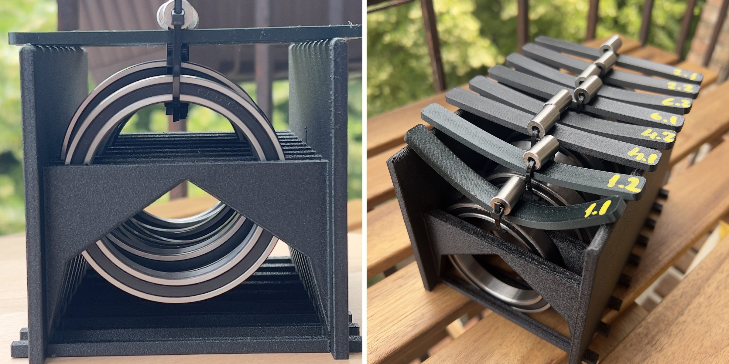
FDM 3D printing has become one of the most practical manufacturing methods for hobby and small-scale robotic projects. It enables rapid prototyping, short design iterations, low production cost, and the ability to manufacture complex parts without specialized tooling. A design can be modified, reprinted, and tested within hours, making it possible to develop robotic mechanisms much faster than with traditional manufacturing methods. It also makes replacement parts and small production runs practical without requiring expensive equipment or molds.
Despite these advantages, FDM printing introduces several engineering challenges. Printed parts are generally less stiff and less strong than machined or molded components, their mechanical properties depend heavily on print orientation because of layer-to-layer anisotropy, and many common materials lose stiffness or deform at relatively modest temperatures. Final performance depends not only on the material itself, but also on printing parameters, part geometry, and post-processing.
For robotic arms, these limitations directly affect real-world performance. Structural parts must withstand repeated loading without excessive bending, maintain dimensional accuracy, resist long-term deformation, and continue to perform reliably in warm environments. They may also experience sudden loads caused by collisions, abrupt motion, contact with mechanical stops, accidental drops, or handling during assembly. A material that performs well under slow or sustained loading may still crack or fail when subjected to impact.
This article compares several commonly available carbon-fiber reinforced filaments together with standard PLA and PETG reference materials. The goal is to evaluate their practical suitability for structural robotic components under realistic printing conditions. Rather than relying solely on manufacturer datasheets, the comparison is based on repeatable measurements of flexural stiffness, thermal resistance, long-term deformation, and impact behavior.
Carbon-Fiber Reinforced Filaments
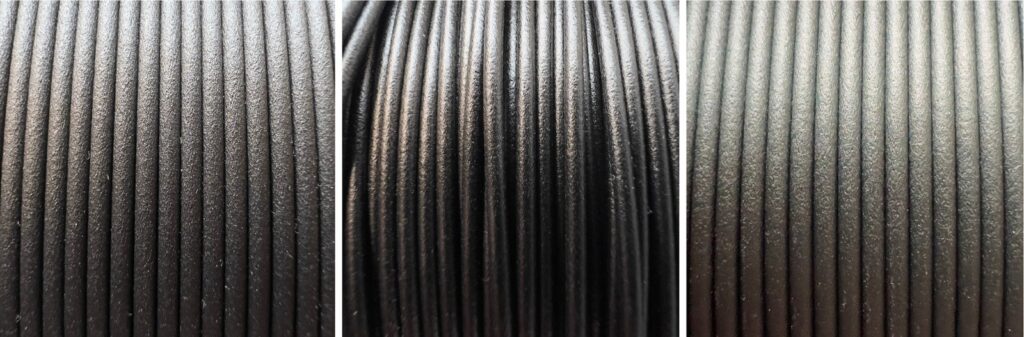
Carbon-fiber reinforced (CF) filaments are composite materials in which short carbon fibers are mixed into a conventional thermoplastic such as PLA, PETG, or PET. The carbon fibers act as a reinforcing filler that modifies the mechanical behavior of the printed part while preserving the ease of FDM printing.
Compared with their non-reinforced counterparts, CF filaments typically produce stiffer parts with improved dimensional stability and reduced thermal expansion. They also have a characteristic matte surface finish that helps hide layer lines and gives printed components a more professional appearance. The actual improvement depends on the base polymer and the amount of carbon fiber used, so PET-CF, PETG-CF, and PLA-CF should be considered different material families rather than variations of the same material.
In this study, we compare carbon-fiber reinforced filaments against standard PLA and PETG reference materials to evaluate how much practical improvement they provide for structural robotic arm components.
Annealing
Annealing is a controlled heat treatment performed below the melting temperature of the polymer. Depending on the material, this process can relieve internal stresses and increase crystallinity, resulting in improved stiffness, thermal resistance, and dimensional stability under load. Many manufacturers of carbon-fiber reinforced filaments recommend annealing for engineering applications to achieve their best mechanical performance.
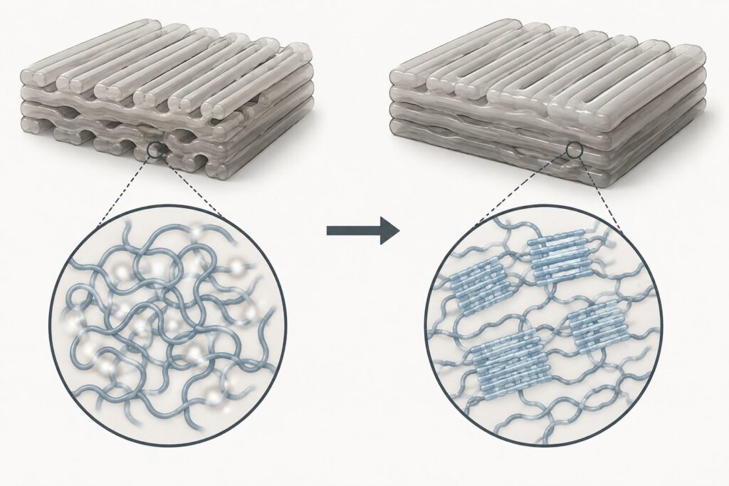
The effect of annealing depends strongly on the base polymer. PET-CF, PETG-CF, and PLA-CF can all respond differently, and the improvement may range from negligible to significant depending on the material formulation and processing conditions. Annealing can also introduce dimensional changes such as shrinkage or warping, which may be undesirable for precision mechanical assemblies.
To evaluate its practical benefits, each carbon-fiber reinforced filament in this study was tested both in its freshly printed condition and after annealing using the manufacturer’s recommended procedure. This allows the effects of annealing to be assessed alongside the additional processing time and potential dimensional changes.
Test Programme Overview
No single material property determines whether a filament is suitable for structural robotic components. A material may be very stiff but deform at elevated temperatures, or it may resist heat well while gradually bending under a sustained load. For this reason, the materials were evaluated using four complementary tests, each addressing a different aspect of practical robotic-arm performance.
- Three-point bending test — measures flexural stiffness by recording specimen deflection under four controlled load levels. The measured data are used to calculate the flexural modulus, allowing the stiffness of different materials to be compared independently of small dimensional variations between specimens.
- Temperature resistance test — evaluates how well a loaded specimen retains its shape at 65–70 °C. This temperature range was selected because servo motors inside robotic joints can reach similar temperatures during continuous operation. If structural parts soften or deform due to motor heat, positioning accuracy and mechanical reliability can deteriorate even without excessive external loads.
- Long-term deformation test — evaluates the material’s resistance to creep under a sustained load. In robotic applications, structural components are often subjected to the same forces for extended periods while supporting the weight of the arm or payload.
- Pendulum impact tests — compare the ability of specimens to absorb energy during sudden loading using both Izod and Charpy configurations. The two configurations apply different support and loading conditions and therefore reveal different aspects of fracture behavior.
Study Limitations
The purpose of this study is to compare the behavior of different filament materials under controlled and repeatable printing and test conditions. To minimize the influence of print geometry, all specimens were printed as solid (100% infill) using identical print settings. This approach makes the results directly comparable between materials, but it does not fully represent the construction of real robotic arm components.
In practical applications, most structural FDM parts are printed with 30–40% infill, multiple perimeters, and geometries optimized for additive manufacturing. Features such as ribs, gussets, box sections, and increased wall thickness can significantly improve stiffness and strength while keeping weight and print time low. Consequently, the absolute deflection measured in this study should not be interpreted as the expected behavior of a finished robotic arm component.
The impact tests were performed using a small, non-certified pendulum test stand intended for comparative material evaluation rather than standardized impact-strength measurement. The recorded results are expressed as a relative absorbed-energy index and should not be interpreted as impact strength in joules or kilojoules per square meter, nor compared directly with manufacturer datasheets or standardized Izod and Charpy values.
Tested Materials
Polymaker Fiberon PET-CF17 was selected as one of the main candidate materials for structural robotic arm parts. PET-CF is a carbon-fiber reinforced PET-based filament, intended to combine the dimensional stability and durability of PET with the increased stiffness provided by carbon fiber reinforcement. For this project, it is interesting because it may offer a good balance between rigidity, printability, and practical strength without moving into more demanding high-temperature engineering polymers.
Bambu Lab PETG-CF is a carbon-fiber reinforced PETG filament. According to Bambu Lab, this material is designed to improve both mechanical performance and surface appearance compared with standard PETG, while maintaining PETG-related advantages such as water, oil, grease, UV, and impact resistance. It is also relevant for our project because it is positioned as a material that can be used for functional parts on consumer-grade printers, while providing a cleaner surface finish and reduced flex compared with regular PETG.
CC3D PETG-CF was included as another PETG-based carbon-fiber composite option. It provides a useful comparison against Bambu Lab PETG-CF because both materials are based on a similar PETG-CF concept, but come from different manufacturers. This makes it possible to check whether the observed behavior is mainly related to the material type itself or whether manufacturer-specific formulation has a noticeable effect on stiffness, surface finish, and printing quality.
Creality Hyper PLA-CF was included as a PLA-based carbon-fiber reinforced material. PLA is usually easy to print and provides good stiffness, while carbon fiber reinforcement can further improve rigidity and reduce visible layer texture. Creality describes its Hyper PLA-CF as having high strength, good layer adhesion, a matte finish, minimal layer texture, and print speeds up to 300 mm/s. For robotic arm parts, this material is interesting because it may provide high stiffness and attractive surface quality while still being relatively easy to print.
Creality PETG was tested as a non-reinforced PETG reference material. PETG is commonly used for functional 3D printed parts because it is tougher and less brittle than standard PLA, while still being printable on typical desktop FDM printers. In this study, it provides a baseline for evaluating how much carbon fiber reinforcement improves stiffness and bending behavior compared with regular PETG.
Soleyin Ultra PLA was tested as a standard PLA reference material. PLA is widely used, easy to print, dimensionally stable, and typically produces clean-looking parts. However, it can be more brittle than PETG-based materials and may be less suitable for parts exposed to higher temperatures or impact loads. In this comparison, it provides a useful baseline for understanding how standard PLA performs against carbon-fiber reinforced options.
Test Stand and Methodology
Three-point Bending Test
The purpose of this test is to measure the elastic deformation of the material under controlled loads. For structural robotic components, stiffness is an important characteristic because excessive deflection can reduce positioning accuracy and repeatability even when the applied loads are well below the failure limit.
For the experimental comparison, we used the three-point bending test stand design published by Stefan Hermann (CNC Kitchen), with minor modifications to match the pin diameter available in our setup. The specimen dimensions were kept identical to the original design to maintain consistent and comparable test geometry.
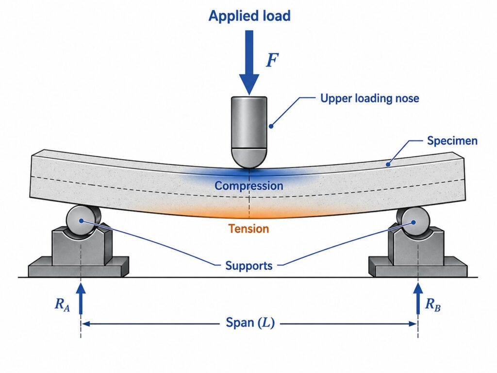
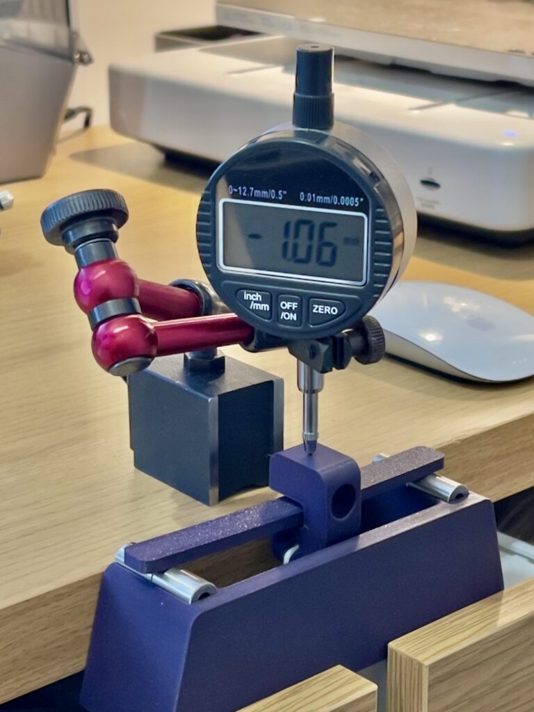
The test stand consists of two lower support pins and one upper loading pin. During the test, the specimen is supported at both ends while a vertical load is applied at the center of the span. The resulting center deflection is measured with a digital dial indicator at predefined load levels. These measurements are then used to calculate the flexural modulus of each specimen and compare the stiffness of the tested materials under identical conditions.
Flexural Modulus Measurement
The main value compared in this test is the flexural modulus, which describes the specimen’s stiffness under bending within the elastic region.
In practical terms, the flexural modulus indicates how much a printed specimen resists bending under a known load. A material with a higher flexural modulus will deflect less under the same force, while a material with a lower flexural modulus will bend more.
For our robotic arm application, this is especially important because we want to minimize structural deflection when the arm is fully extended and carrying a standard load.
During the three-point bending test, we measure four reference load points for each specimen:
(F₁, δ₁), (F₂, δ₂), (F₃, δ₃), (F₄, δ₄)
where F is the applied force and δ is the measured center deflection.
From these points, we calculate the slope of the force-deflection curve:
k = ΔF / Δδ
where k is the bending stiffness of the specimen. It can be estimated using the first and last measured points:
k = (F₄ − F₁) / (δ₄ − δ₁)
or by fitting a straight line through all four measured points.
For a rectangular specimen in a three-point bending test, the flexural modulus is calculated as:
E = (kL³) / (4bh³)
where L is the distance between the lower support pins, b is the specimen width and h is the specimen thickness in the bending direction.
Actual Test Conditions
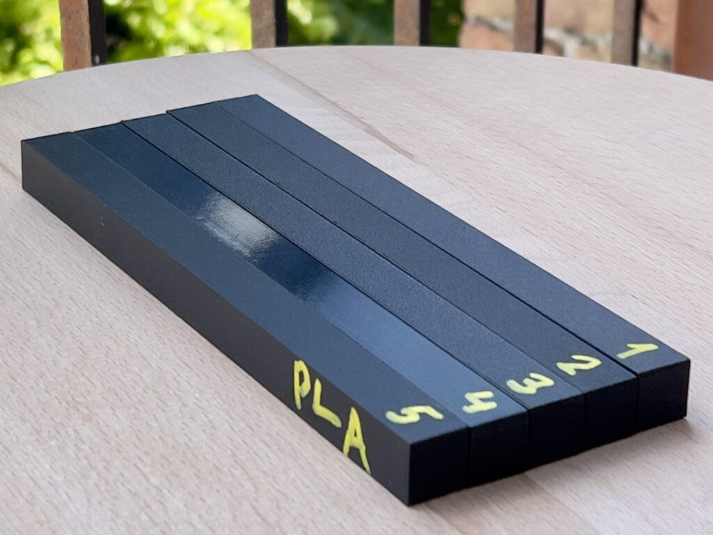
The specimens were tested in a three-point bending setup using identical printing and measurement conditions for all materials. At least two specimens were prepared for each test condition. For carbon-fiber reinforced filaments, both normal (freshly printed) and annealed conditions were evaluated using at least two specimens each, while the reference PLA and PETG materials were tested in their normal printed state. Each specimen was printed as a solid part with 4 walls, a 0.2 mm layer height, and a 0.4 mm nozzle. The nominal specimen dimensions were 120 × 12 × 4 mm, while the actual dimensions of each specimen were measured individually and used in the flexural modulus calculation. The distance between the two lower support pins was 102.5 mm.
| Parameter | Value |
|---|---|
| Filament drying duration | 6 h |
| Walls | 4 |
| Infill | 100% |
| Nozzle diameter | 0.4 mm |
| Layer height | 0.2 mm |
| Nominal specimen size | 120 × 12 × 4 mm |
| Support span L | 102.5 mm |
| Reference mass per load step | 0.350 kg |
| Force per load step | 3.43 N |
Table 1. Three-point bending print and measurement conditions.
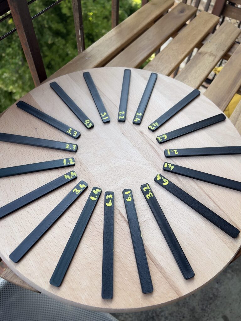
Loading was applied in four steps using repeatable reference weights. The reference mass was approximately 0.35 kg, corresponding to 3.43 N per step under standard gravity; the four force levels were approximately 3.43 N, 6.86 N, 10.30 N, and 13.73 N. Center deflection was measured with a digital dial indicator at each step. Normal specimens were tested directly after printing; Fiberon PET-CF17, Bambu Lab PETG-CF, Creality PLA-CF, and CC3D PETG-CF were also tested as separately annealed specimens.
| Filament | Print temp (°C) | Anneal temp (°C) | Anneal time |
|---|---|---|---|
| Fiberon PET-CF17 | 300 | 110 | 6 h |
| Bambu Lab PETG-CF | 255 | 65–70 | 6 h |
| Creality PLA-CF | 220 | 60 | 6 h |
| CC3D PETG-CF | 255 | 65–70 | 6 h |
Table 2. Annealing schedules used for carbon-fiber reinforced specimens.
Additional Test Conditions
The temperature-resistance test used the same specimen geometry as the three-point bending test. Each specimen was supported over a 100 mm span and loaded with a 110 g hanging mass (approximately 1.08 N) at the center. The specimens were placed in a laboratory oven at 65–70 °C for 1 hour, after which the permanent deflection was measured and compared with the initial condition.
The long-term deformation test was performed using the same three-point support arrangement with a 1 kg central load (approximately 9.81 N). The initial deflection was measured immediately after applying the load, followed by a second measurement after 30 minutes to quantify time-dependent deformation (creep). The load was then removed, and the specimen was allowed to recover for 2 minutes before the final residual deflection was recorded. This procedure makes it possible to distinguish between elastic deformation, creep under sustained load, and permanent deformation after unloading.
Pendulum Impact Test
The purpose of the impact test was to compare how much energy the different filament specimens could absorb during a sudden load. This complements the three-point bending test, which evaluates deformation under gradually applied force. A material may be very stiff during normal loading but still fracture abruptly when struck, while a more ductile material may bend further and absorb more energy before failure. Impact testing is therefore useful for robotic components that may experience collisions, contact with mechanical stops, accidental drops, or other short-duration loads.
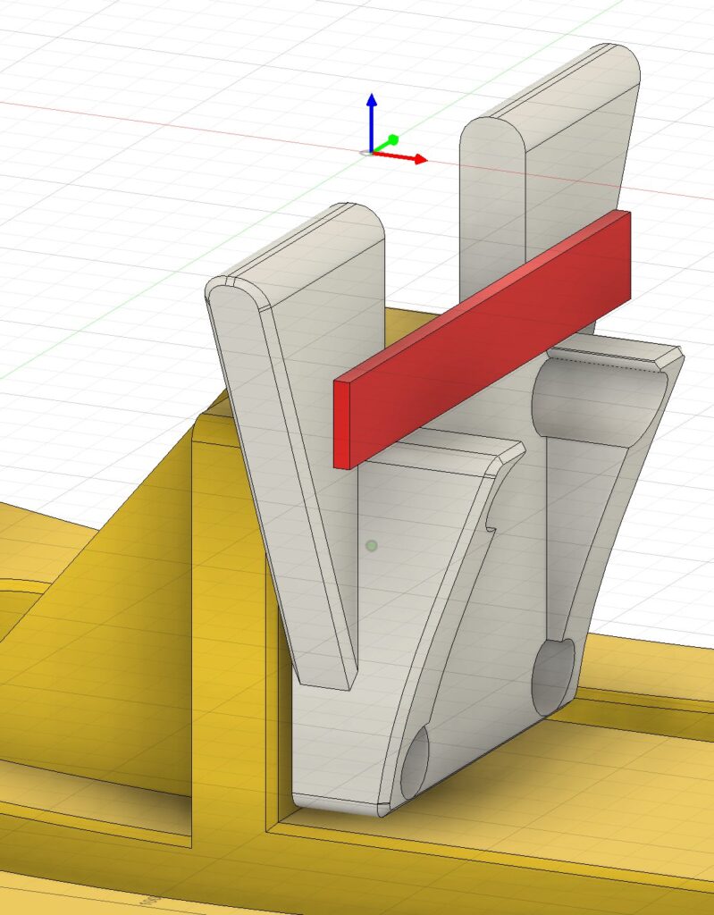
The test stand was built using the open-source Izod Impact Test project published on Printables as the reference design. It uses a pendulum released from a repeatable starting position and a mechanical scale that indicates how far the pendulum continues after striking the specimen. A greater reduction in the pendulum’s remaining travel indicates that more energy was absorbed by the specimen during deformation and fracture. The same stand was configured to perform both Izod-style and Charpy-style tests, allowing the materials to be compared under two different support and loading arrangements.
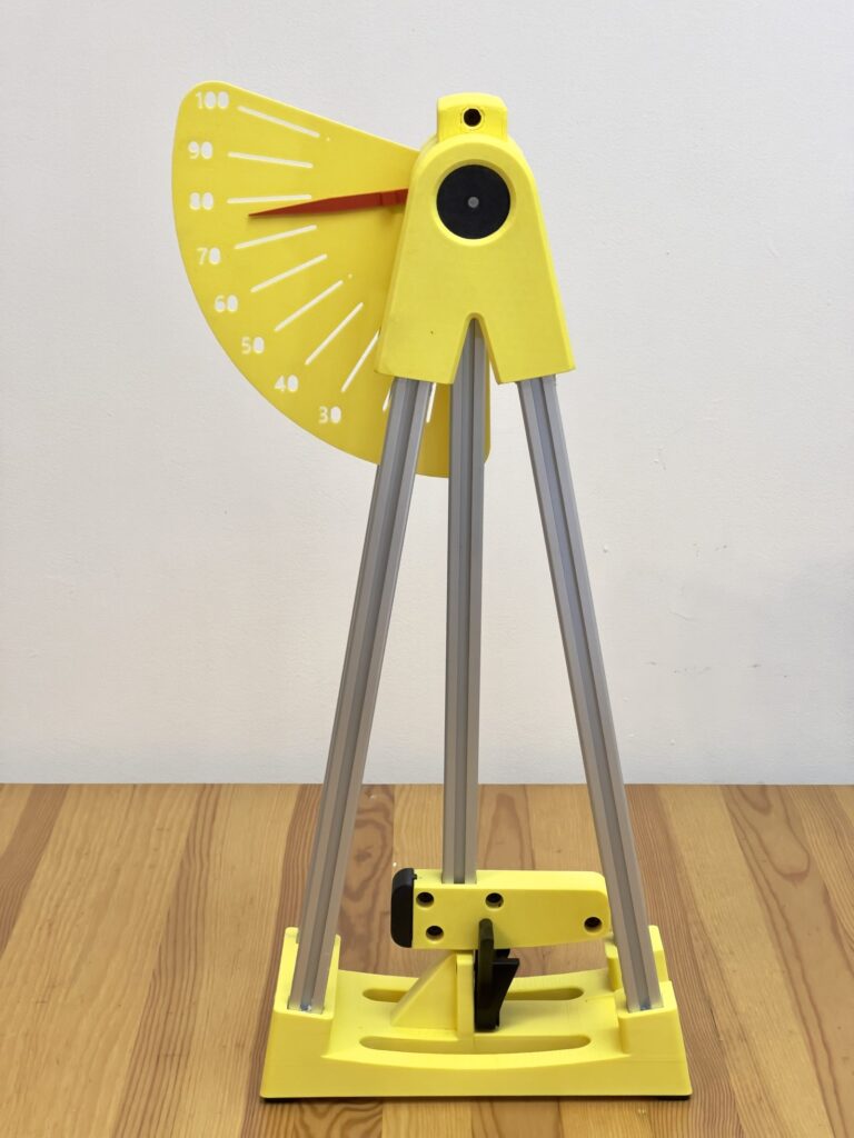
Pendulum impact test in action.
In the Izod configuration, the specimen was positioned vertically and clamped at one end, leaving the upper section unsupported. The pendulum struck the exposed part of the specimen, producing a dynamic cantilever-bending load. This configuration concentrates stress near the clamped region and provides a useful comparison of resistance to sudden localized loading. Specimen position, clamping depth, pendulum release position, and impact direction relative to the printed layers were kept consistent between tests.
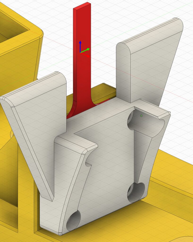
In the Charpy configuration, the specimen was placed horizontally across two supports and struck by the pendulum between them. This produces a dynamic bending load similar in general arrangement to a three-point bending test, but applied at impact speed. The specimen can deform across the supported span before breaking, so the result may reflect both fracture resistance and the material’s ability to absorb energy through bending. Izod and Charpy results were evaluated separately because the two configurations create different stress distributions and should not be treated as directly interchangeable measurements.
The pendulum scale was used as a relative measurement rather than as a calibrated energy reading. The relative absorbed-energy index was calculated as 100 minus the pendulum reading after impact, so a higher value indicates greater energy absorption within this test setup. The results should therefore be interpreted as comparisons between specimens tested on the same stand and under the same conditions, rather than as standardized impact-strength values in joules or kilojoules per square meter.
The same filament types and printing conditions used in the other experiments were retained for the impact specimens. Standard PLA and PETG were tested in their normal printed condition, while each carbon-fiber reinforced filament was tested both as printed and after annealing. The annealed specimens were prepared using the material-specific temperatures and durations listed previously in Table 2.
Three-Point Bending Stiffness Results
Among the freshly printed specimens, Creality PLA-CF and Fiberon PET-CF17 showed the highest stiffness, with calculated flexural moduli of 2898 MPa and 2891 MPa, respectively. Both materials exhibited the lowest deflection under load, making them the strongest performers in the as-printed condition. CC3D PETG-CF ranked third with 2319 MPa, outperforming both standard PETG and standard PLA.
The reference materials demonstrate that carbon-fiber reinforcement does not guarantee improved performance on its own. Creality PETG (2029 MPa) and Soleyin PLA (1862 MPa) were noticeably stiffer than Bambu Lab PETG-CF (1595 MPa), despite containing no carbon-fiber reinforcement. This demonstrates the importance of the base polymer and overall material formulation rather than carbon-fiber content alone.
| # | Filament | Flexural modulus E (MPa) | Max. deflection (mm) |
|---|---|---|---|
| 1 | Creality PLA-CF Normal | 2898.32 | 1.58 |
| 2 | Fiberon PET-CF17 Normal | 2891.47 | 1.50 |
| 3 | Soleyin PLA | 1862.16 | 2.40 |
| 4 | Bambu Lab PETG-CF Normal | 1594.96 | 2.80 |
| 5 | Creality PETG | 2029.01 | 2.40 |
| 6 | CC3D PETG-CF Normal | 2319.00 | 2.00 |
| 7 | Fiberon PET-CF17 Annealed | 3480.37 | 1.20 |
| 8 | Bambu Lab PETG-CF Annealed | 1831.19 | 2.50 |
| 9 | Creality PLA-CF Annealed | 2948.27 | 1.50 |
| 10 | CC3D PETG-CF Annealed | 2495.82 | 1.90 |
Table 3. Three-point bending stiffness and maximum deflection results.
The force-deflection curves show the same trends visually. Fiberon PET-CF17 (annealed) consistently exhibited the lowest deflection across the entire load range, followed by Creality PLA-CF. Bambu Lab PETG-CF remained the most flexible material both before and after annealing, while the remaining materials occupied intermediate positions.
Effect of Annealing on Flexural Stiffness
Annealing increased the flexural stiffness of every tested carbon-fiber reinforced filament, although the magnitude of the improvement depended strongly on the material. As shown in the charts, the response ranged from almost no measurable change to a substantial increase in stiffness.
Fiberon PET-CF17 benefited the most from annealing, with its flexural modulus increasing from 2891 MPa to 3480 MPa, a gain of 20%. This moved it from being virtually tied with Creality PLA-CF in the as-printed condition to becoming the stiffest material in the entire comparison.
Bambu Lab PETG-CF also showed a significant improvement, increasing by 15% from 1595 MPa to 1831 MPa. Although it remained the least stiff of the tested carbon-fiber composites, the improvement demonstrates that annealing can noticeably increase the rigidity of PETG-CF materials.
CC3D PETG-CF exhibited a more moderate response, with an 8% increase in flexural modulus (2319 MPa to 2496 MPa).
Creality PLA-CF changed by only 2% (2898 MPa to 2948 MPa), indicating that the recommended annealing procedure provides little additional stiffness for this material.
These results show that the benefit of annealing cannot be generalized across all carbon-fiber reinforced filaments. While every material became stiffer, the improvement varied from negligible to substantial depending on the base polymer and material formulation. For applications where maximum stiffness is the primary objective, Fiberon PET-CF17 gained the greatest practical benefit from annealing under the tested conditions.
Thermal Resistance
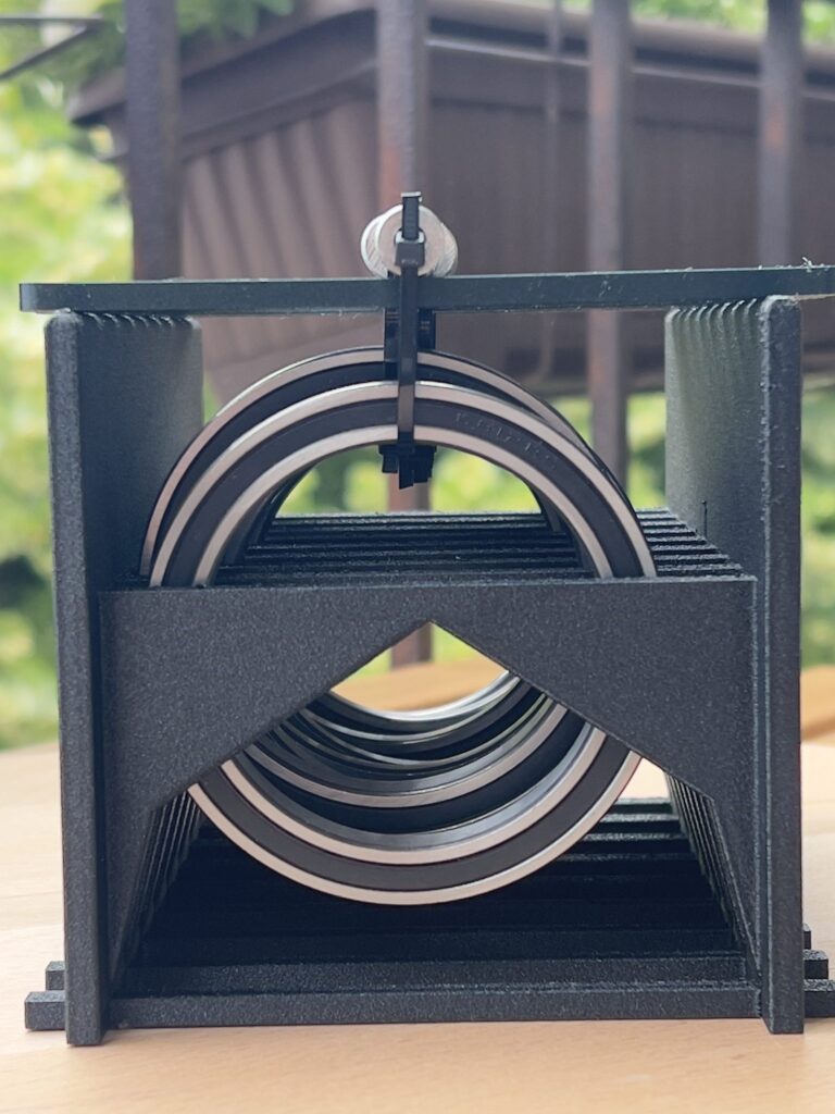
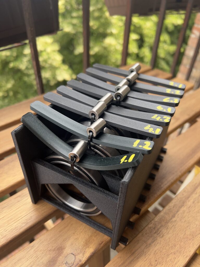
Servo motors can reach temperatures of 65–70 °C during continuous operation, especially when operating under sustained load or inside enclosed robotic joints. Structural parts located close to the motors must therefore retain their shape at elevated temperatures to avoid loss of positioning accuracy or mechanical interference. This test evaluates the practical ability of each material to maintain its geometry while supporting a constant load at temperatures representative of real robotic operation.
The specimens were tested at 65–70 °C for 1 hour using the same nominal geometry as the three-point bending specimens. Each specimen was supported over a 100 mm span and loaded with a 110 g central weight (approximately 1.08 N). The measured center deflection after the test was used as an indicator of thermal resistance under load.
| Filament | Normal (mm) | Annealed (mm) | Improvement |
|---|---|---|---|
| Fiberon PET-CF17 | 3.4 | 0.3 | 11.3× |
| Bambu Lab PETG-CF | 5.9 | 2.5 | 2.4× |
| CC3D PETG-CF | 6.0 | 2.3 | 2.6× |
Table 4. Thermal deflection at 65–70 °C after 1 hour under 1.08 N load.
Creality PLA-CF, Soleyin PLA, and unfilled Creality PETG deformed too severely under these conditions to provide meaningful comparable measurements.
The results show that annealing has a much greater effect on thermal performance than on room-temperature stiffness. Fiberon PET-CF17 exhibited the largest improvement, with deflection decreasing from 3.4 mm to 0.3 mm, representing an 11-fold increase in shape retention. Both PETG-CF materials also benefited substantially from annealing, reducing their deflection by more than half, although they remained noticeably less stable than annealed Fiberon PET-CF17.
The remaining materials were unable to maintain their shape under the test conditions. This does not necessarily mean they are unsuitable for every application, but it indicates that they should not be selected for structural components located near continuously operating servo motors unless the operating temperature can be kept well below the tested range.
Long-Term Deformation
Robotic arm components are often subjected to sustained loads while supporting the weight of the arm or payload. Even if a material is sufficiently stiff, it may gradually deform over time and fail to fully recover after the load is removed. This test evaluates the material’s resistance to time-dependent deformation (creep) and its ability to return to its original shape after prolonged loading.
Each specimen was loaded with a 1 kg central weight for 30 minutes using the same three-point support arrangement described previously. The initial deflection was recorded immediately after applying the load, followed by a second measurement after 30 minutes to quantify creep. After removing the load, the specimen was allowed to recover for 2 minutes, and the remaining residual deflection was measured.
| Filament | Initial deflection (mm) | After 30 min (mm) | Residual deflection (mm) |
|---|---|---|---|
| Fiberon PET-CF17 N | 1.08 | 1.18 | 0.10 |
| Fiberon PET-CF17 A | 0.82 | 0.92 | 0.02 |
| Bambu Lab PETG-CF N | 1.88 | 2.12 | 0.20 |
| Bambu Lab PETG-CF A | 1.80 | 2.00 | 0.15 |
| CC3D PETG-CF N | 1.60 | 1.64 | 0.14 |
| CC3D PETG-CF A | 1.57 | 1.63 | 0.20 |
| Creality PLA-CF N | 1.15 | 1.37 | 0.29 |
| Creality PLA-CF A | 1.00 | 1.13 | 0.40 |
| Soleyin PLA N | 1.60 | 2.05 | 0.30 |
| Creality PETG N | 1.70 | 1.83 | 0.10 |
Table 5. Long-term deformation under 1 kg load and residual deflection after 2 minutes of recovery.
Among all tested materials, Fiberon PET-CF17 demonstrated the best long-term dimensional stability. Annealing reduced its initial deflection from 1.08 mm to 0.82 mm, while creep during the 30-minute loading period remained low (0.10 mm) in both conditions. More importantly, the residual deflection decreased from 0.10 mm to only 0.02 mm, indicating almost complete recovery after unloading.
Bambu Lab PETG-CF also benefited from annealing, reducing its residual deflection from 0.20 mm to 0.15 mm. In contrast, CC3D PETG-CF showed little benefit in this test, with residual deflection increasing slightly from 0.14 mm to 0.20 mm after annealing. Creality PLA-CF exhibited the largest residual deformation among the carbon-fiber composites, increasing from 0.29 mm to 0.40 mm after annealing.
These results highlight an important difference between stiffness and long-term dimensional stability. Although annealing increased the flexural modulus of every tested carbon-fiber filament, it did not universally improve recovery after sustained loading. For robotic arm components expected to carry loads for extended periods, Fiberon PET-CF17 was the only material that showed a clear improvement across stiffness, thermal resistance, and long-term dimensional stability.
Impact Test Results
The pendulum impact tests were used to compare how the tested materials responded to sudden loading in two different configurations. In the Izod configuration, each specimen was loaded as a vertically clamped cantilever, while in the Charpy configuration, each specimen was supported horizontally at both ends and struck between the supports. Because the two configurations create different stress distributions and allow different amounts of specimen deformation, their results are presented separately.
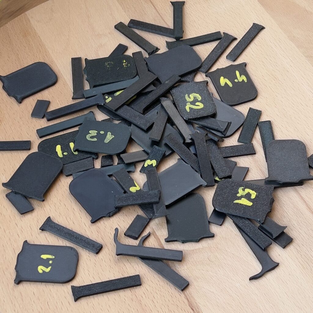
The recorded values are expressed as a relative absorbed-energy index calculated from the pendulum scale. A higher value indicates that more energy was removed from the pendulum during the impact event. These values are intended only for comparison between specimens tested on the same stand and should not be interpreted as standardized impact-strength values.
| Filament | Condition | Izod | Charpy |
|---|---|---|---|
| Creality PLA-CF | Normal | 20 | 12 |
| Fiberon PET-CF17 | Normal | 15 | 5 |
| Soleyin PLA | Normal | 17 | 15 |
| Bambu Lab PETG-CF | Normal | 29 | 65 |
| Creality PETG | Normal | 24 | 60 |
| CC3D PETG-CF | Normal | 20 | 8 |
| Fiberon PET-CF17 | Annealed | 8 | 10 |
| Bambu Lab PETG-CF | Annealed | 25 | 22 |
| Creality PLA-CF | Annealed | 18 | 12 |
| CC3D PETG-CF | Annealed | 21 | 13 |
Table 6. Relative absorbed-energy index from Izod and Charpy impact tests. Higher values indicate greater energy absorption.
The clearest result was the substantially higher Charpy energy absorption of Bambu Lab PETG-CF and standard Creality PETG in the normal condition, with relative absorbed-energy indices of 65 and 60. All other normal specimens remained at 15 or below in the same configuration. The Izod results were more closely grouped, with Bambu Lab PETG-CF again recording the highest value, followed by standard PETG.
Annealing produced several substantial changes, most notably the reduction in the Charpy result of Bambu Lab PETG-CF from 65 to 22 and the reduction in the Izod result of Fiberon PET-CF17 from 15 to 8. By contrast, small differences of approximately 5% between normal and annealed specimens fall within the practical limitations of this test setup and should not be interpreted as confirmed improvement or deterioration.
Discussion of the Results
Stiffness vs Impact Resistance
The results demonstrate that stiffness and impact resistance are separate material properties and should not be treated as interchangeable. The three-point bending test measures how strongly a specimen resists elastic deformation under gradually applied load, whereas the pendulum test evaluates how much energy it absorbs during a sudden impact. A material can therefore be highly rigid during normal operation but still fail abruptly when struck.
This distinction is particularly clear when comparing Fiberon PET-CF17 with the PETG-based materials. Fiberon was one of the stiffest specimens and became the stiffest after annealing, but its impact results were relatively low. In contrast, Bambu Lab PETG-CF was the least stiff CF material in the bending test but recorded the highest impact indices among the normal specimens. Standard Creality PETG followed the same general pattern, combining moderate stiffness with very high Charpy energy absorption.
These results show that material selection should depend on the expected loading conditions of the component. Rigid links, servo mounts, and structures that must preserve positioning accuracy benefit primarily from high stiffness and low creep. Covers, guards, gripper components, and parts exposed to collisions may benefit more from a ductile PETG-based material capable of absorbing impact energy. Where both properties are important, part geometry, wall thickness, local reinforcement, and replaceable protective features may be more effective than selecting a material based on a single test result.
Carbon-Fiber Reinforced vs Standard Filaments
The results confirm that carbon-fiber reinforcement can significantly improve the performance of printed structural components, but the improvement is not guaranteed simply by adding carbon fiber. The base polymer and overall material formulation appear to have a greater influence than the presence of carbon fibers alone.
Among the freshly printed specimens, Fiberon PET-CF17 and Creality PLA-CF were substantially stiffer than the standard PLA and PETG reference materials. CC3D PETG-CF also outperformed standard PETG in the three-point bending test. Bambu Lab PETG-CF, however, was less stiff than both reference materials, demonstrating that a carbon-fiber reinforced filament is not automatically more rigid than an unfilled polymer.
The impact results reveal another important difference. Standard Creality PETG achieved one of the highest Charpy absorbed-energy indices in the study, only slightly below Bambu Lab PETG-CF and far above the other CF composites. This indicates that carbon-fiber reinforcement does not necessarily improve resistance to impact and may reduce the material’s ability to deform and absorb energy before fracture. The effect varies strongly by formulation: Bambu Lab PETG-CF showed the highest impact-energy absorption among the normal specimens, while CC3D PETG-CF and Fiberon PET-CF17 produced much lower Charpy results.
Carbon-fiber reinforcement also produced a noticeably better surface finish. All tested CF materials exhibited a uniform matte appearance with reduced visibility of layer lines, resulting in printed parts that required little or no cosmetic post-processing. Overall, CF filaments should be considered distinct engineering materials with specific combinations of stiffness, thermal stability, creep resistance, and impact behavior rather than simple upgrades over their non-reinforced counterparts.
Annealing in Practice
Annealing improved the stiffness and thermal resistance of all tested carbon-fiber reinforced materials, but the magnitude and overall usefulness of the change depended strongly on the filament. The largest benefit was observed for Fiberon PET-CF17, which improved its flexural stiffness, thermal resistance, and long-term dimensional stability. Bambu Lab PETG-CF and CC3D PETG-CF also became stiffer and retained their shape better at elevated temperatures, although their improvements were less comprehensive.
The long-term deformation and impact tests show that annealing should not be viewed as a universal upgrade. Increased stiffness did not always result in better recovery after sustained loading, and impact resistance could either improve or decrease depending on the material and test configuration. The most significant negative result was observed for Bambu Lab PETG-CF, whose Charpy absorbed-energy index decreased from 65 to 22 after annealing. Fiberon PET-CF17 also showed a substantial reduction in its Izod result.
Annealing should therefore be selected according to the dominant requirement of the finished component. It is highly beneficial when thermal stability, stiffness, and resistance to gradual deformation are the primary objectives, especially for Fiberon PET-CF17. For parts expected to absorb collisions or sudden loads, however, annealing may reduce useful ductility and should be evaluated carefully. Its effectiveness depends on the base polymer, fiber content, manufacturer formulation, and the balance of properties required for the specific robotic component.
Conclusions
This study compared several commercially available carbon-fiber reinforced filaments using four complementary tests: three-point bending stiffness, temperature resistance under load, long-term deformation, and pendulum impact testing in Izod and Charpy configurations. The results show that no single property is sufficient to identify the best filament for every robotic-arm component. Stiffness, thermal stability, resistance to creep, and impact tolerance must be considered separately.
For rigid structural parts located near servo motors or expected to carry sustained loads, Fiberon PET-CF17 delivered the strongest overall performance. It combined very high stiffness with excellent thermal stability and the lowest residual deformation after prolonged loading. Annealing provided a substantial additional benefit, making it the most suitable material in this study for links, servo mounts, and other precision-critical structural components. Its comparatively low impact results, however, mean that it is less suitable where collision resistance is the dominant requirement.
CC3D PETG-CF is a practical secondary option where moderate stiffness, improved thermal resistance after annealing, PETG-based printability, and good surface quality are valued. It did not match Fiberon in stiffness, heat resistance, or long-term dimensional stability, and its impact performance remained limited, but it still provides a useful compromise for general structural parts.
For components exposed to sudden bending, collisions, or accidental impact, Bambu Lab PETG-CF and standard Creality PETG showed the strongest Charpy results in the normal condition. Their lower stiffness and weaker thermal performance limit their use in precision structural parts near warm motors, but they may be better suited to covers, guards, gripper elements, bumpers, and other parts intended to absorb energy rather than remain highly rigid.
Creality PLA-CF provided excellent stiffness in the as-printed condition but showed poor resistance to elevated temperature and only modest impact-energy absorption. It is therefore best suited to passive or lightly loaded structures operating well below the softening range of PLA, where high rigidity and easy processing are more important than thermal or impact performance.
Annealing should not be treated as a universal improvement. It significantly enhanced stiffness and thermal stability for several materials, especially Fiberon PET-CF17, but it did not consistently improve long-term recovery and could reduce impact-energy absorption. Heat treatment should therefore be selected according to the dominant requirement of the final component rather than applied automatically.
Overall, the best material depends on the expected failure mode. Fiberon PET-CF17 is the preferred choice for rigid and thermally loaded structures, CC3D PETG-CF is a practical secondary structural option, and Bambu Lab PETG-CF or standard PETG may be preferable for parts where impact tolerance is more important than maximum stiffness. Material selection should be made component by component, based on operating temperature, sustained load, required positioning accuracy, and exposure to sudden impacts.
Log in to leave a comment.