Mobile Robot Concept Design Development
 3576
3576
In May we completed a first variation of the full robot design. I want to show step by step what we started from and what we finally get.
Initial Requirements
- A 3D design concept needs to be created with consideration for the technical specifications of the structure.
- The model should be showcased in an environment – indoors, controlled by a person using VR Oculus Quest 3.
- Source files must be provided.
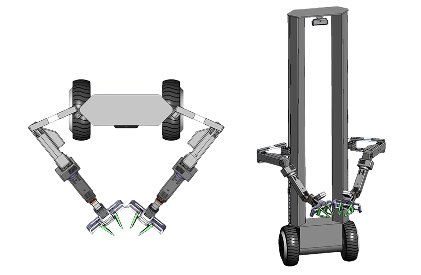
Initial concept. Design provided from our engineer
External Parameters
- Matte black color. Alternative color schemes may be considered: white, yellow.
- Frame dimensions: 350 mm to 400 mm x (1300 mm – 1400 mm including wheel height).
- Operating format – like a Segway.
- The view of the upper П-shaped frame from the front and back should be identical.
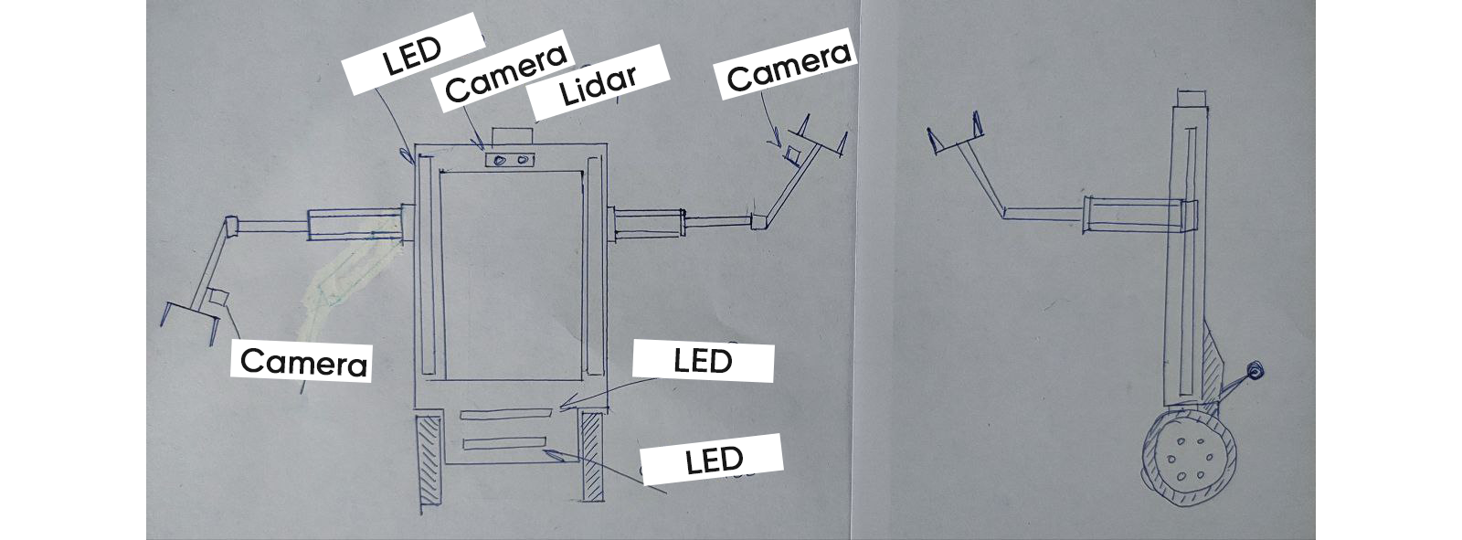
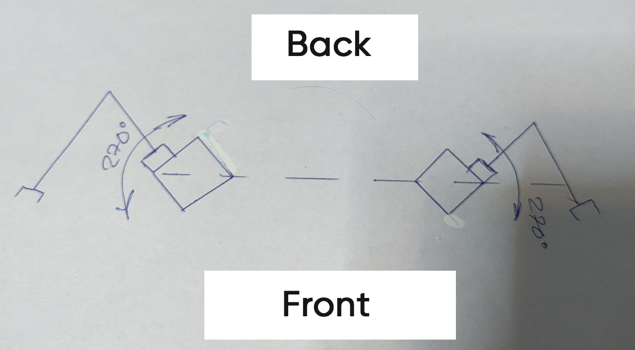
- A depth camera and LiDAR should be installed on the upper frame.
- LED strips should be installed on the side frames.
- LED strips should also be installed on the lower platform.
- Depth cameras similar to Intel RealSense D405 should be mounted on the manipulators.
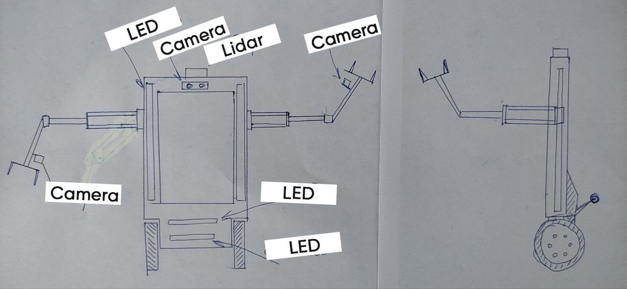
Sketch shows position of detectors
Balancing Mechanism
The tail will be in a lowered position all the time, and will have a straight shape resembling the letter П, with a roller at each end. The rollers are non-driven.
Balancing mechanism. Lower position. Profile view
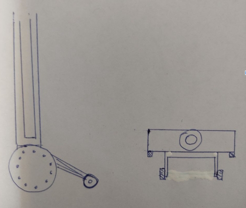
Balancing mechanism
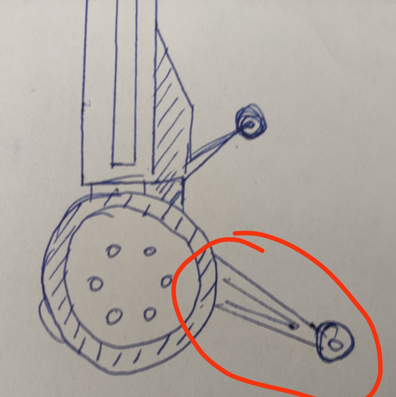
Wheels
Swiveling wheels, like in the image: 3-inch Small Industrial Caster Wheels
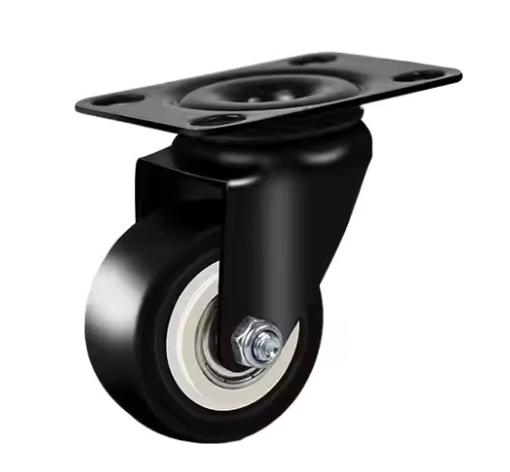
Robot back wheels
Manipulators
- The manipulators extend to the full height of the pole.
- Height – 1300 mm
- Length – 650 mm
- The appendage on the second joint should be adjusted; the engineer will determine how to remove or shift the structure inward.
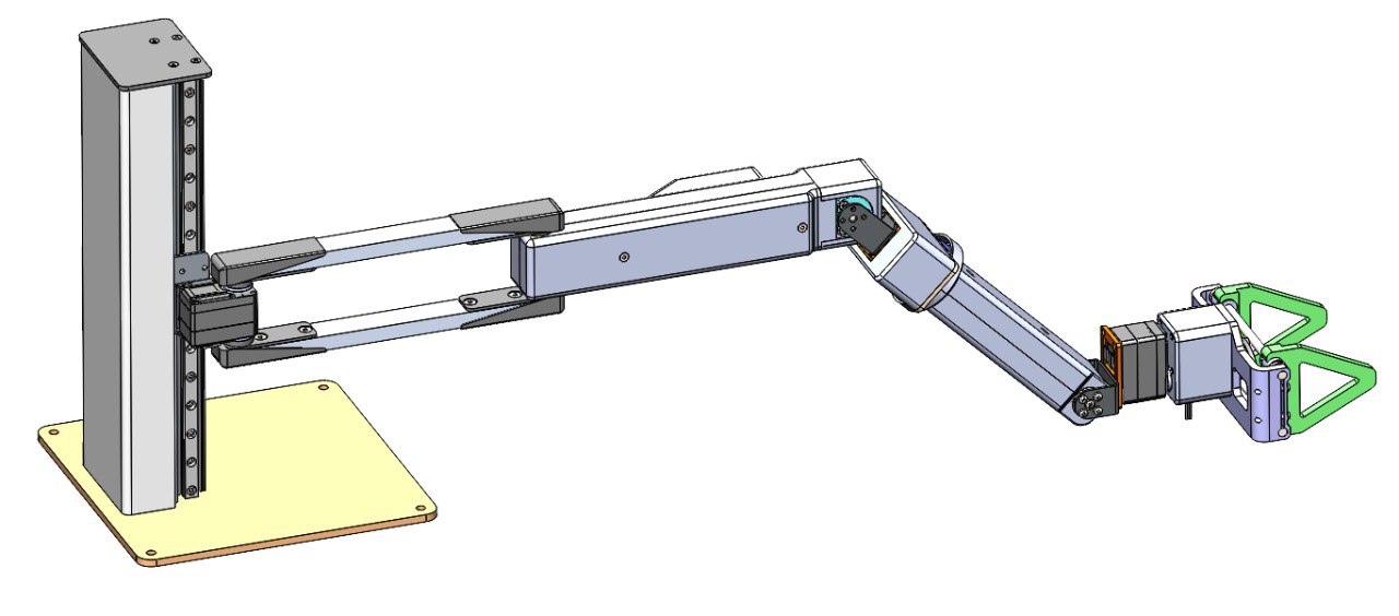
Robot arm
Design of the Gripper
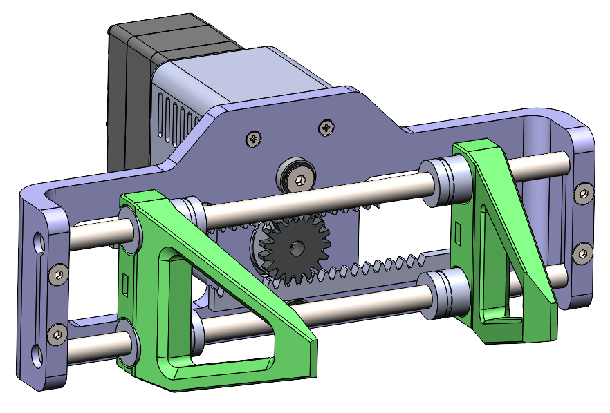
Parallel gripper design
Position of Manipulator Poles
- The poles should be turned at a 45-degree angle to ensure maximum reach.
Main frame poles angle
An idea of such poles angle position is to provide as much working space as possible for manipulators.
Top Sensors
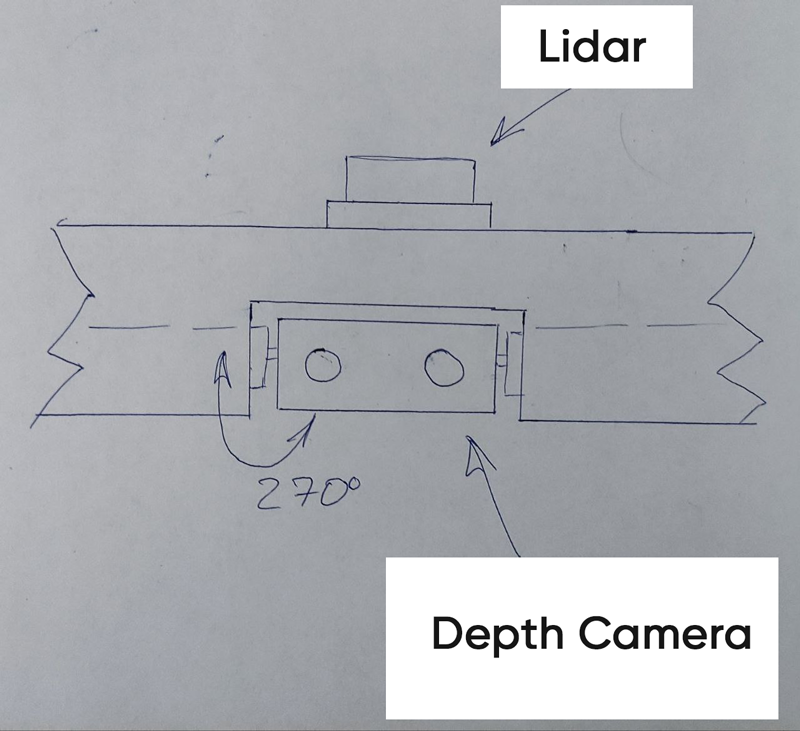
Top sensors
- Depth camera should be rotated back and forth.
- Initially I thought to use 3d lidars, so I placed one on the top.
Lower Wheel Motors
- Size: 8.5 inches
- 8.5-inch wheels for electric scooters
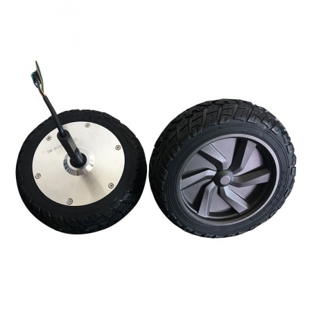
Front electric motor wheels
First version of the robot's main frame
First version of the robot’s main frame. Front view
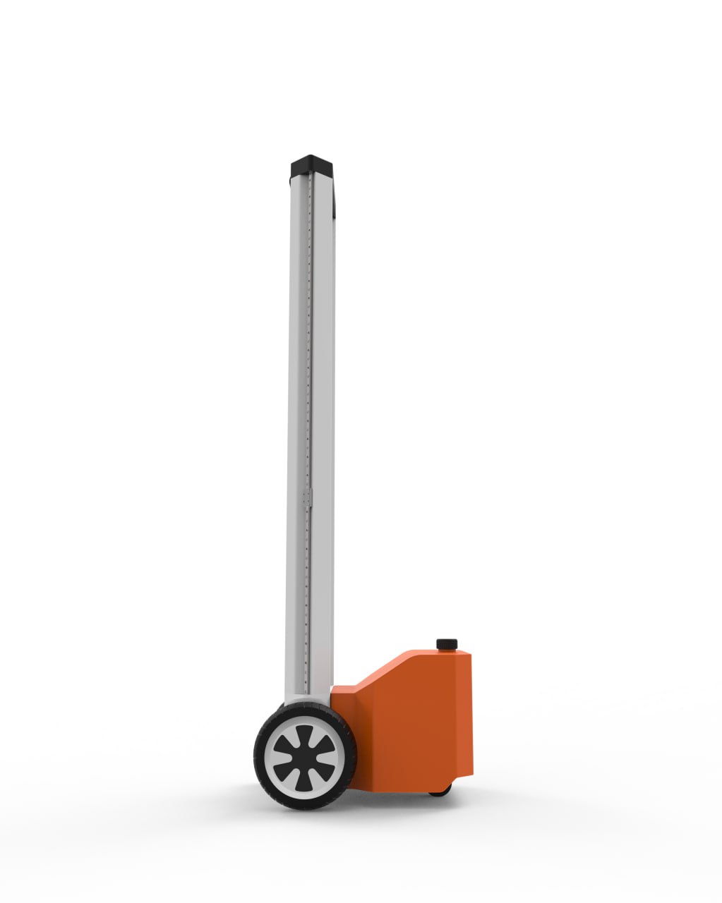
First version of the robot’s main frame. Profile view
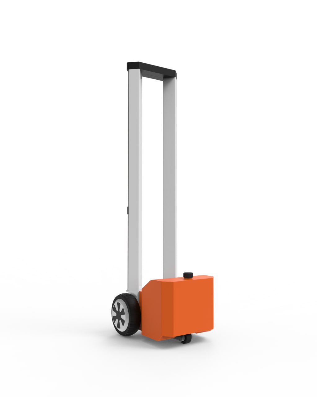
First version of the robot’s main frame. Back view
In this version:
- We decided to use heavy back instead of adaptive tail. Initially I thought to use water tank, because we need around 20kg weight to compensate for the forward tipping moment when the arms are extended with maximum weight.
- Designer used orange color to make robot visible from a long distance.
First version of the robot's main frame
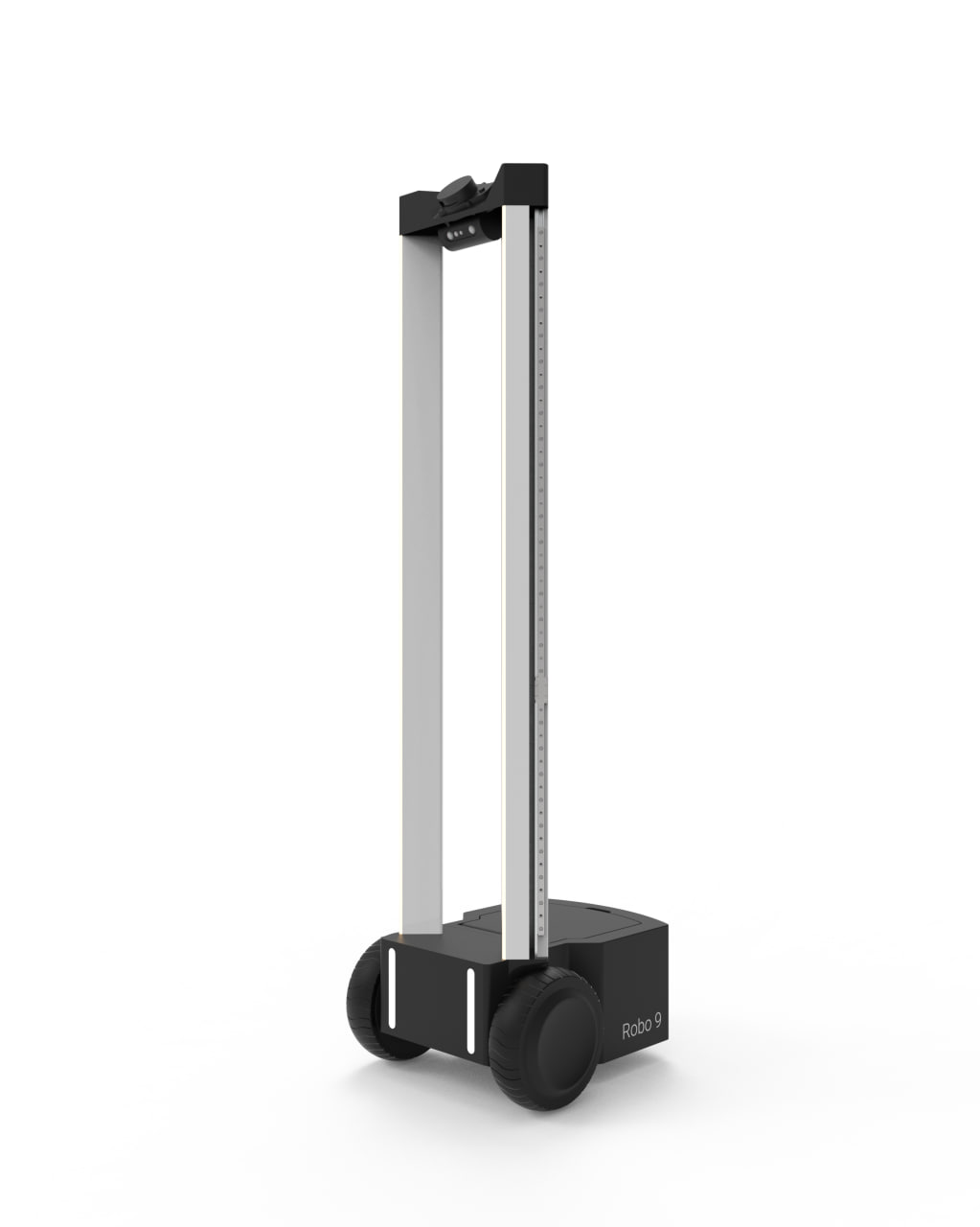
Second version of the robot’s man frame. Front view
Second version of the robot’s man frame. Front view
Updates
- Switched to black color, because engineering tough plastics mostly have black color.
- Decided to use flat surface of the back to allow future users to place something on top.
- Instead of water tank we found heavy duty batteries, that we can use to compensate for the forward tipping moment.
- Designer added front lights at mobile base, lidar and depth camera at the top of the frame.
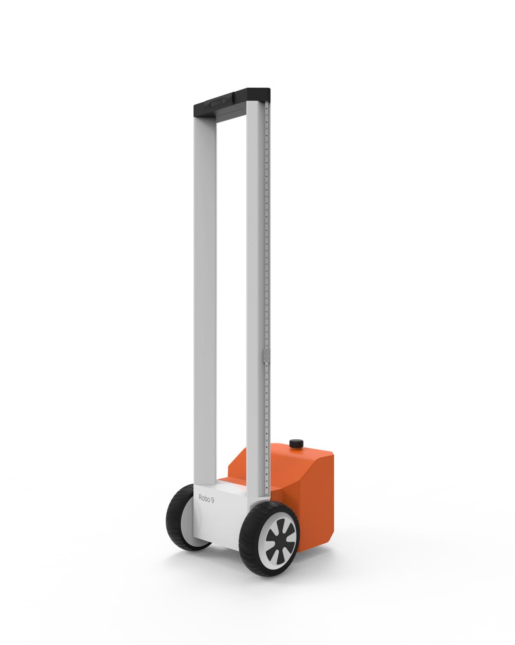
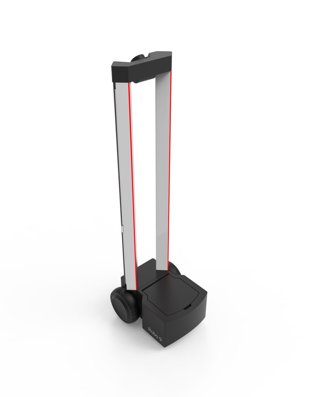
Latest version of the concept design. But not final...
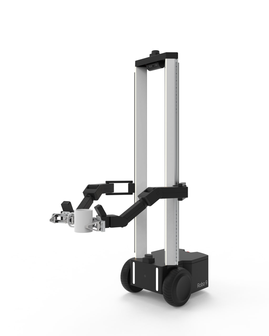
Robot V0 Design Concept. Front view
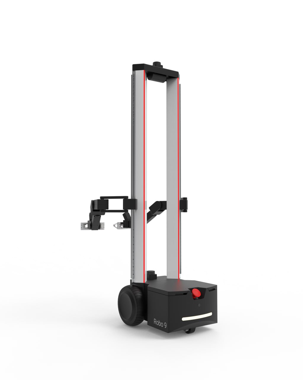
Robot V0 Design Concept. Back view
- Designer added 2 manipulators.
- Back light.
- Stop button to prevent any possible extreme behavior. Like on following viral video:
- Second lidar
Notes
Final design will differ from current.
- Currently we are working on compensation of backslash of motors using double servo design. So final arms would have different design.
- Instead of 3d lidars we probably will use combination of sensors like 2D, 1D lidars, ultrasonic distance sensors
really thoughtful piece on the design side, i think people underestimate how much the early form decisions constrain everything downstream from sensor placement to thermals
the transition from sketch to foam model to functional prototype is exactly the kind of process content i wish more hardware teams shared, most just drop the finished thing
how many physical prototypes did you go through before settling on this form factor?
Five foam-and-print mockups before the first functional one, then three functional iterations. Most of the changes were about cable routing and serviceability, not looks.
whats the design process for deciding wheel layout vs tracks at the concept stage?
We start from the target environment: flat indoor floors push us to wheels for efficiency and quiet operation, while uneven terrain would justify tracks. For this concept it’s indoor-first, so wheels won.
Got it, appreciate the reply.
love seeing the messy prototype photos and not just the polished render
is the styling driven by function or are some of these surfaces purely aesthetic? curious where the line is for you
It’s mostly function-led — vents, sensor windows and grip points come first — but we do treat the visible surfaces as a chance to make it approachable, which matters a lot in a home or classroom setting.
Would be great to see a prototype!
the industrial design language here is really cohesive, nice