Choosing Cost-Effective Electric Motors for the Robot Arm
 5760
5760
In this article, I want to discuss how the selection of the most important component of the robotic manipulator – the electric motors – took place. I will begin with an overview of the solutions chosen by Trossen Robotics in the Viper X 300 S manipulator, which is one of the most popular solutions for research projects such as Aloha 2 and Pi0.
Servo Drives in the Viper X 300 S Manipulator
Servo Drives in the ViperX 300 S Manipulator
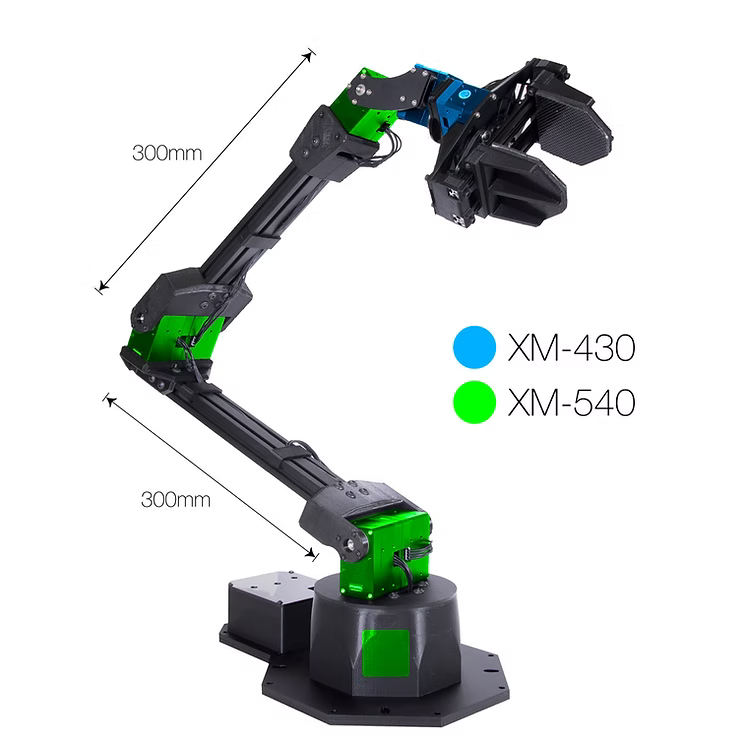
First of all, we examined existing solutions for manipulators with 6DOF (six degrees of freedom). The manipulator I focused on is the Viper X 300 S, as it was originally included in the list of materials for Aloha 2. The manufacturer has made part of the documentation and drawings available, and I thought it would be great to reuse these solutions.
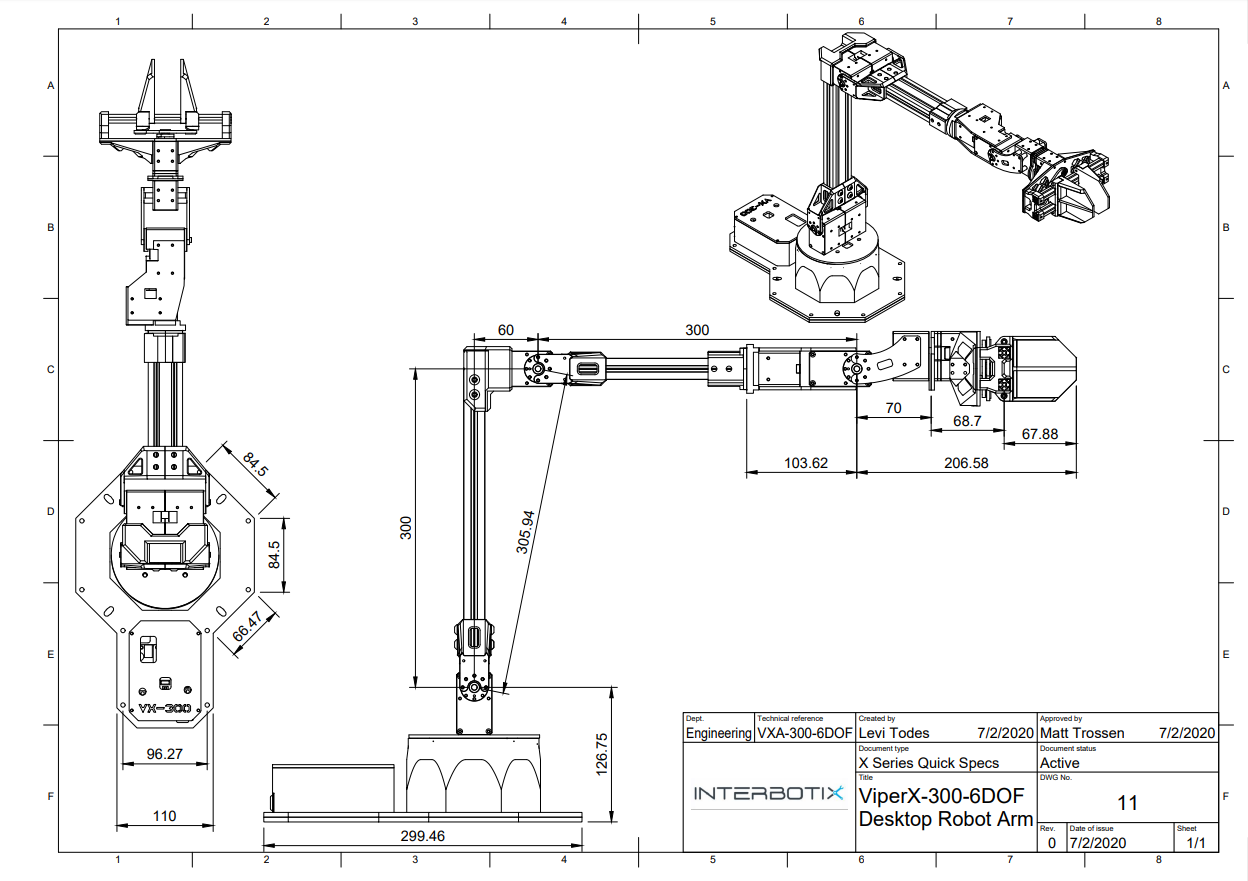
ViperX-300 6DOF Desktop Robot Arm
The main challenge in creating an affordable manipulator is finding accessible drives with high torque. In the Viper X 300 S, Trossen Robotics used DYNAMIXEL XM430-W350 servo motors with a stall torque of 4 Nm, priced at $290, and DYNAMIXEL XM540-W270-T/R servo motors with a stall torque of 10 Nm, priced at $430. A total of 9 servo motors are required to create such a manipulator, bringing the total cost to $3,590, which is no longer considered affordable.
| ID | Joint Name | Servo | Baudrate | Price |
| 1 | waist | XM540-W270 | 1Mbps | $430 |
| 2 | shoulder | XM540-W270 | 1Mbps | $430 |
| 3 | shoulder_shadow | XM540-W270 | 1Mbps | $430 |
| 4 | elbow | XM540-W270 | 1Mbps | $430 |
| 5 | elbow_shadow | XM540-W270 | 1Mbps | $430 |
| 6 | forearm_roll | XM540-W270 | 1Mbps | $430 |
| 7 | wrist_angle | XM540-W270 | 1Mbps | $430 |
| 8 | wrist_rotate | XM430-W350 | 1Mbps | $290 |
| 9 | gripper | XM430-W350 | 1Mbps | $290 |
| Total | $3590 | |||
An engineer (hereafter referred to as Alan) who is currently working on the project made a kinematic calculation for a manipulator arm with an overall length of 700 mm and a load capacity of 750 grams.
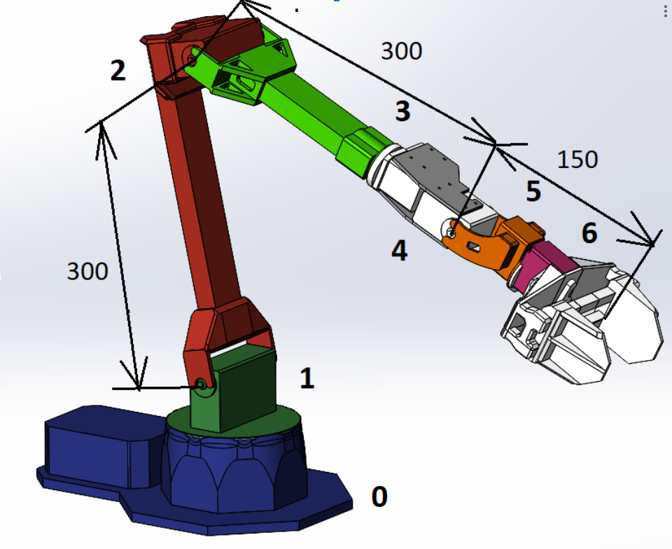
ViperX 300 Joints
| Version 1.1 – 0.75 kg | |||||||
| Inertia safety factor – 1,5 | |||||||
| Joint | Axis | Shoulder, cm | Load | kg*sm | kg*sm | Weight on the end | kg |
| Base | 0 | 0 | 3 | 7 | |||
| Shoulder | 1 | 20 | 1,8 | 54,0 | 81 | cargo | 0,75 |
| Elbow | 2 | 20 | 1,5 | 30,0 | 45,0 | gripper | 0,25 |
| Forearm | 3 | 0 | 1,2 | 0 | 0 | servo | 0,1 |
| Hand -1 | 4 | 15 | 1,1 | 16,5 | 24,8 | ||
| Hand – 2 | 5 | 0 | 1 | 0 | 0 | ||
| Gripper | 6 | 0 | 0,75 | 0 | 0 | ||
According to the calculations, we need drives at the base of the arm with a required torque of 81 kg*cm, or 8 Nm in total. This means that if we install two servo motors at the base, each with a stall torque of 4 Nm, it should be sufficient. However, it is crucial to understand that if a servo motor has a stall torque of 4 Nm, its peak effective torque—at which it can operate steadily—will typically be about half of that value, as illustrated in the Performance Graph.
XM430-W350 Performance Graph
This limitation needs to be taken into account to ensure that the manipulator can handle the desired loads without overstraining the motors.
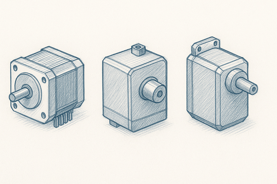
Types of Servo Drives
I started looking at what types of motors are used in budget manipulators.
- Stepper motors such as Nema 17, Nema 23.
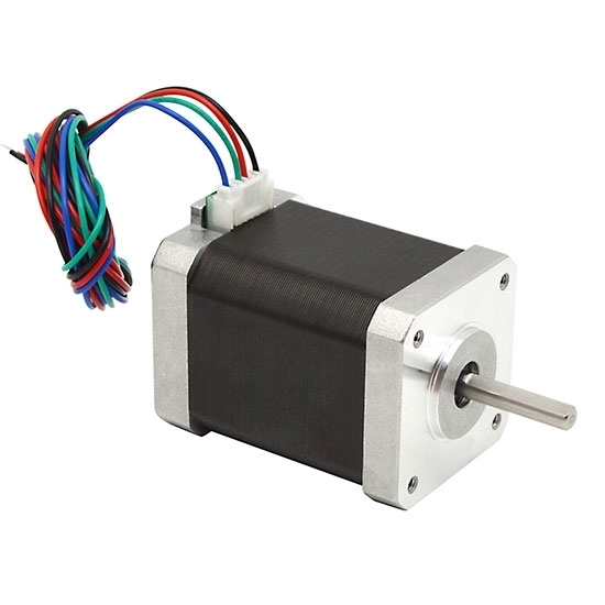
Nema 17 Stepper Motor
- PWM (Pulse-Width Modulation) motors, such as the Dsservo 160 kg*cm.
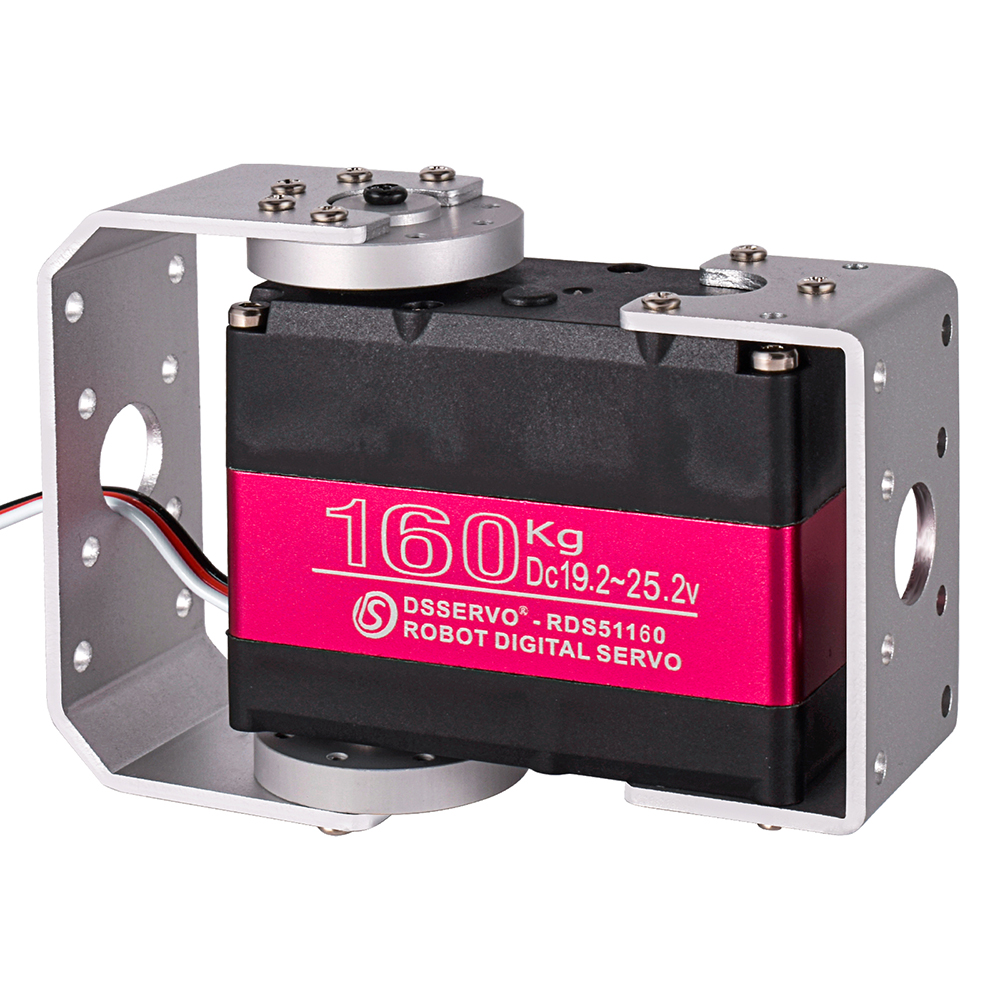
Dsservo DS51160MG
- UART (Universal Asynchronous Receiver/Transmitter) motors, such as the Feetech STS 3215-C01.
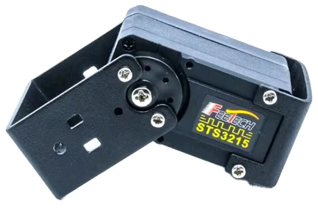
Feetech-STS3215
What key indicators will we focus on?
- Torque
- Precision
- Current, voltage
- Feedback (temperature, current, position sensors)
- Weight
- Cost
What is engine torque?
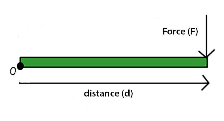
Torque = Force (F) × distance (d)
Engine torque is the force that makes the engine rotate. You can think of it as the “twisting force” that helps the engine do its work. The higher the torque, the easier it is for the engine to accelerate and lift heavy loads. It is important for cars: good torque helps with better acceleration and climbing.
The torque of an engine is defined as the product of the force applied and the distance from the pivot point to where that force is applied. The formula is as follows:
Torque = Force × Distance (or torque = F × d). The higher the torque, the greater the leverage this engine can work with.
Positioning Accuracy
In robotics, this is one of the most important indicators, as the task of the servo drive is to accurately position the arm in space, and the more precise we can achieve this, the better. The main characteristics for a robotic arm are repeatability and absolute accuracy.
Repeatability
This refers to the ability of the manipulator to return to the same point in space after multiple cycles. It is measured in millimeters (for example, ±0.01 mm). The smaller the value, the higher the accuracy of the movement repetitions.
Absolute Accuracy
This is the ability of the manipulator to reach a specified point in space relative to a global coordinate system. It is measured in millimeters (for example, ±0.1 mm). Absolute accuracy is usually worse than repeatability due to the accumulation of errors in kinematics.
Feedback Sensors
Position Sensors
- Hall Effect Sensors: These sensors determine the position of the rotor. They use magnets to understand where the moving part of the motor (the rotor) is located or how fast it is rotating.
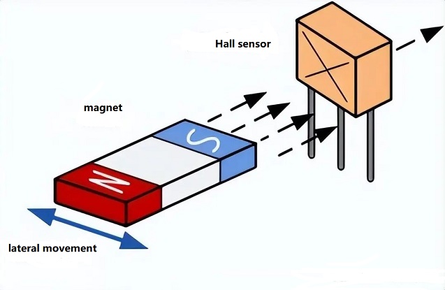
Hall Effect Sensor Main Principle
- Resolvers: These provide precise determination of the angle of rotation. They function as accurate “angular detectors,” indicating the exact position of the motor rotor.
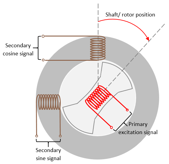
Resolver Main Principle
- Potentiometers: This device, similar to a volume control, changes resistance as the motor moves, indicating the position of its shaft.
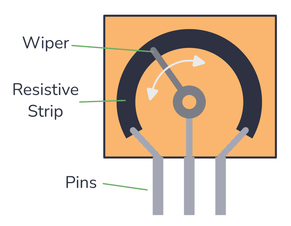
Potentiometer Main Principle
- Optical Encoders: They provide information about the position and speed of the rotor. Imagine a small wheel with slots. Light passes through these slots, and we count these flashes to determine how many times the motor has turned and where it is located.
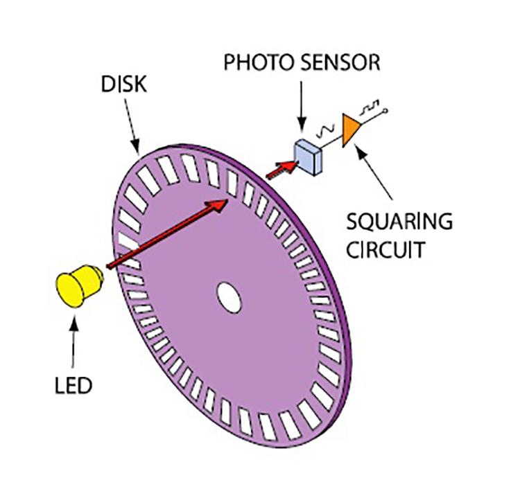
Optical Encoder Main Principle
- Magnetic Encoders: They also measure position and speed using magnetic fields. They utilize magnets to track the motor’s position and work well even in challenging conditions.

Magnetic Encoder Main Principle
Current Sensors
- Current Measurement Sensors: These measure the current consumed by the motor to assess the load.
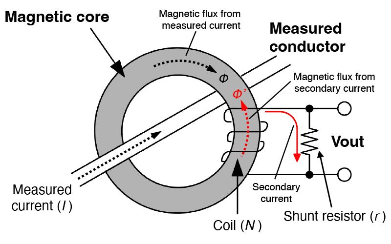
Current Measurement Sensor Main Principle
Temperature Sensors
- Thermocouples or Thermistors: These monitor the temperature of the motor to prevent overheating.
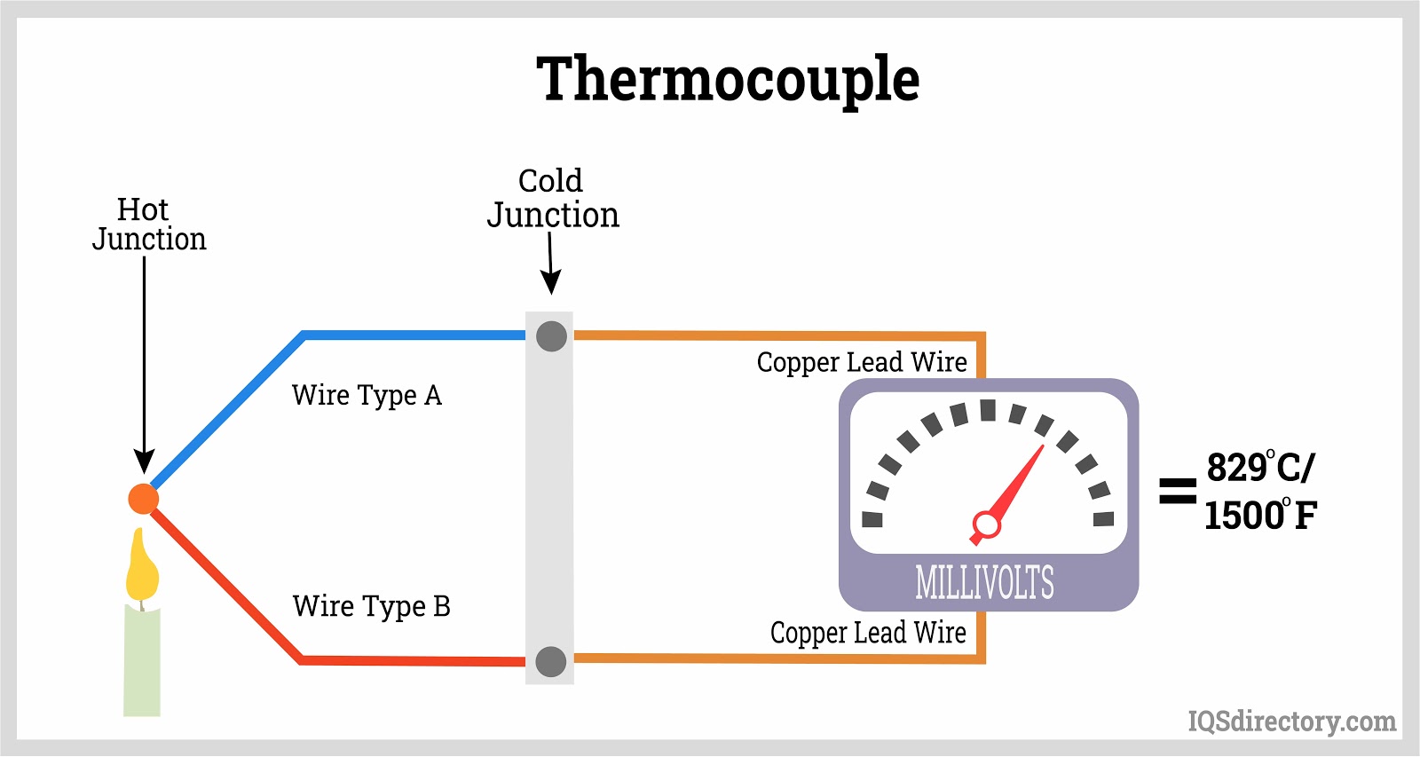
Thermocouple Main Principle
Stepper Motors
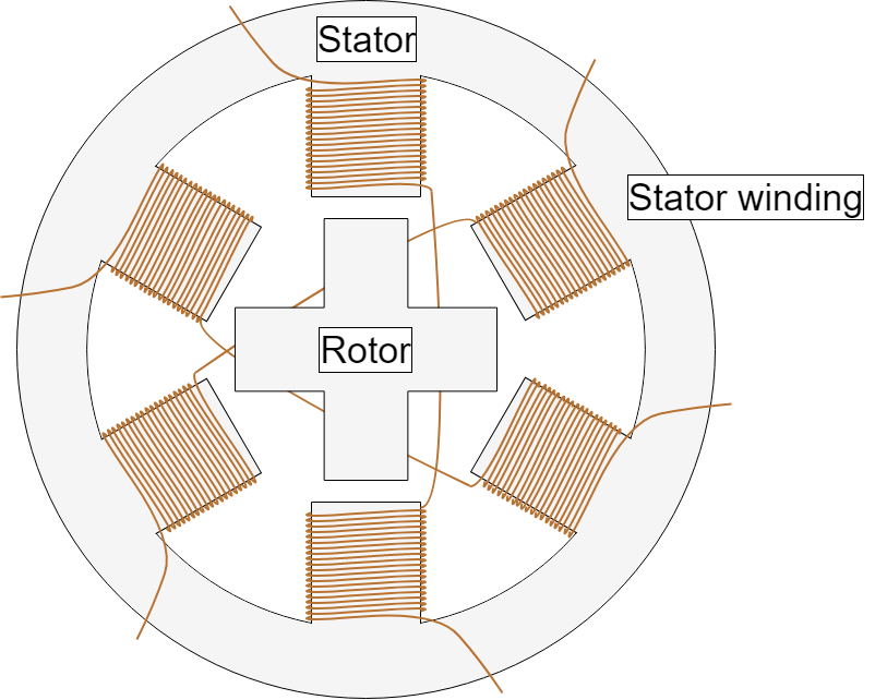
Stepper Motor Schema
I did not go into detail about stepper motors due to their size, greater weight, lower torque, and low positioning accuracy.
For example, the Nema 17 Bipolar 1.8° 36Ncm can be compared to the budget UART servo motor ST3215-C018 in a similar price range. The Nema 17 weighs 280 grams and has a torque of 36Ncm (or 3.6 kg·cm) with a step angle of 1.8 degrees.
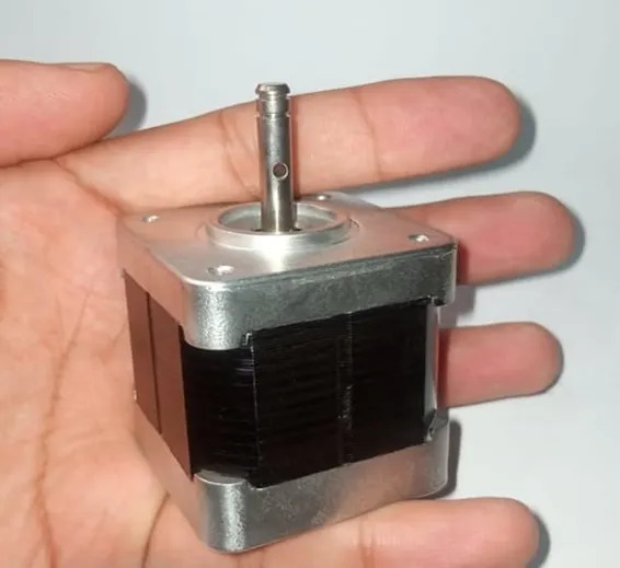
Nema 17 Stepper Motor
The servo motor in a similar price range, Feetech ST3215-C018, weighs 55 grams, has a torque of 30 kg·cm, and a positioning accuracy of 0.09 degrees.
| Motor Model | Mass/Grams | Rated Torque/Kg | Accuracy/Degrees | Price/$ |
| Nema 17 Bipolar 1.8deg 36Ncm | 280 | 3,6 | 1,8 | 10,75 |
| Feetech ST3215-C018 | 55 | 15 | 0,09 | 16.45 |
So, if we compare based on the key characteristics that we took into account for our arm, which are weight * torque * positioning accuracy, the difference would be (280 / 55) * (15 / 3.6) * (1.8 / 0.09) = ~424 times. Of cource we can’t compare these types of motors only based on these 3 parameters, we missed a number of other factors like RPM, reduction ratio, noise, backlash. If we add them to comparison table, then difference won’t be significant. For some scenarios Nema motor might be better choice.
PWM vs UART
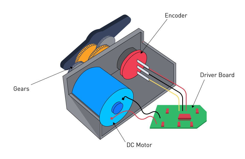
Servo Driver Basic Schema
I started looking for affordable servos with high torque. The first thing I found was the Dsservo RDS51150, which has a torque of 150 kg·cm, a very high value for this type of servo. A feature of these servos is that they include a control system with a position sensor based on a potentiometer, which complicates the task of obtaining feedback and controlling the position due to the limited accuracy and sensitivity of the potentiometer.
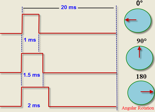
Pulse-Width Modulation Principle
A characteristic of the operation of Dsservo motors is that they are PWM (Pulse-Width Modulation) motors. This is a method of controlling the power of electrical current by pulsing it on and off. They lack a magnetic encoder to transmit the current position of the shaft and do not have a built-in controller. These motors are not suitable for use in robotic systems where positioning accuracy and feedback are important.
I thought about how to compensate for these shortcomings. We found a suitable magnetic encoder, the AS5600, with 4600 positions. Plus, we needed a controller that could operate on PWM.
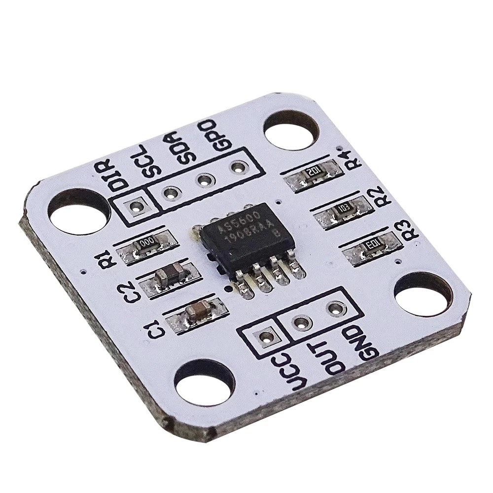
AS5600 Magnetic Encoder
Alan recommended a good programmer who works in robotics. He suggested abandoning PWM in favor of UART (Universal Asynchronous Receiver/Transmitter) motors, as the additional complexities in software control and technical implementation would likely not be justified. The reliability of inexpensive PWM motors compared to UART is also in question, since the built-in potentiometers for speed detection often fail.
| PWM | UART | |
|---|---|---|
| Operating Principle | Analog: control of power through pulse width modulation | Digital: command transmission via serial interface |
| Main Task | Smooth speed regulation (DC motors) | Precise positioning (servo drives) |
| Accuracy | High for speed, low for position | High for positioning (step accuracy) |
| Communication | Unidirectional (control → motor) | Bidirectional (supports feedback) |
| Hardware Complexity | Minimal (driver + PWM generator) | High (controller with UART + protocol) |
| Energy Efficiency | Higher (direct power control) | Lower (depends on protocol and processing) |
| Typical Applications | Drills, fans, servo drives | 3D printers, CNC, robotics |
In the case of UART motors, we can connect them in series on a single bus, providing feedback on position, current strength, and motor temperature. However, the cost of such motors with similar torque will be significantly higher.
I started considering suitable UART motors, and after careful examination, I settled on the following types: Feetech 30 kg and 50 kg. When purchasing in batches of 100 pieces, the cost will be $12 each.
Servo Motor Feetech STS3215-C018. Torque and Backlash
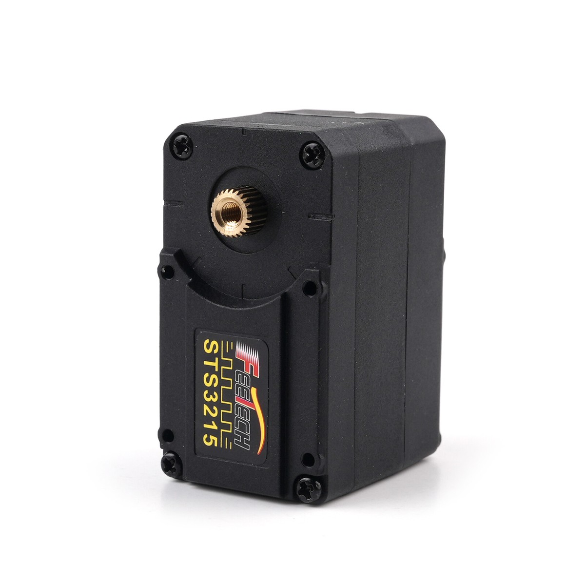
Feetech STS3215 Servo Motor
The engineer prepared a kinematic calculation of the system based on the torque values indicated on the seller’s website. At this point, Alan pointed out that the torque specified for the motor is the stall torque, which is the maximum torque at which the motor can operate before it stops completely under load. Therefore, we cannot use this torque for considering the lifting capacity of the manipulator, as it simply won’t move under such a load.
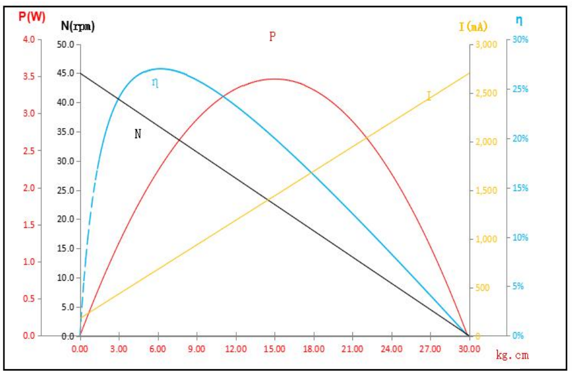
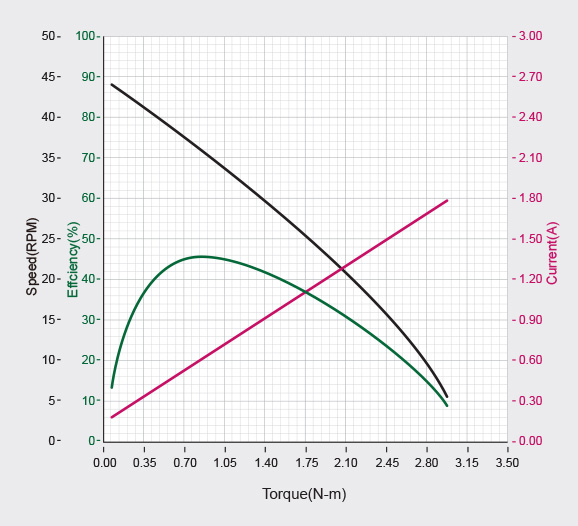
Torque, power, efficiency, current graph
The following graphs come to the rescue, showing that the maximum operational torque to focus on is actually half of what is stated—this can be seen in the middle of the graph. Specifically, it shows 15 and 25 kg·cm. This means that if we use a lever arm of 700 mm with two motors rated at 50 kg, we would be able to show a maximum lifting capacity of 240 grams, which is insufficient.
Last month, Alan ordered several samples for testing at home. Here’s what we noticed.
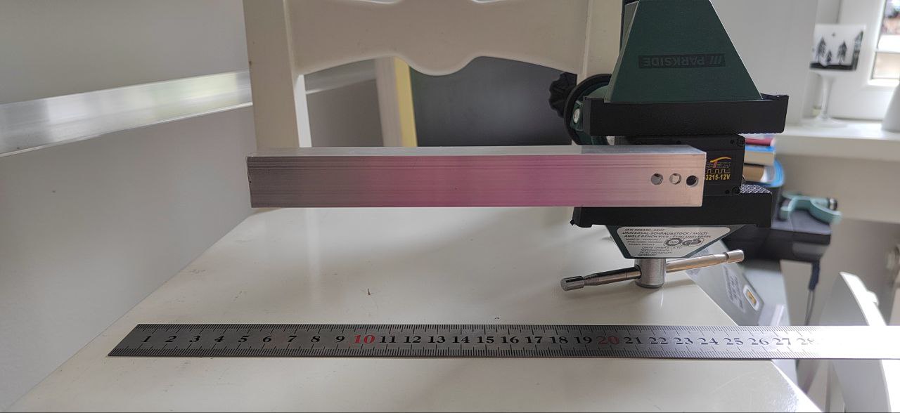
Feetech STS3215 Backlash Measurement
The backlash in the servo motor is twice as much as stated (≤0.5°) in the technical documentation, measuring 3 mm at a 160 mm arm length, which corresponds to approximately 1.072 degrees.
Secondly, we measured the temperature under constant load.
Test 1: Overheating Check During Static Load Retention.
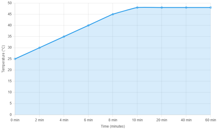
Static Load Overheat Test. Feetech STS3215
The arm with a dumbbell was positioned sideways, holding a 1 kg weight at a 15 cm lever arm, resulting in a torque of 15 kg·cm. Over 10 minutes, the temperature rose to 48°C and remained stable for an hour without further increase.
Test 2: Oscillation in a ±90-Degree Range. Temperature measurement
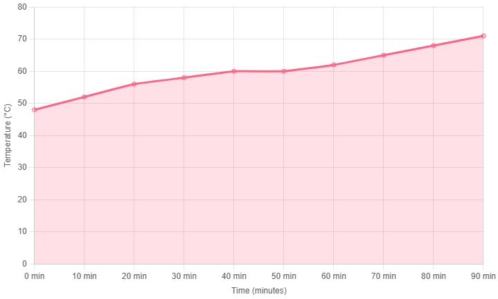
Oscillation in a ±90-Degree Range. Temperature test. Feetech STS3215
Starting at 48°C, the temperature reached 60°C after 50 minutes. For the next 20 minutes, the temperature did not increase. The oscillation speed was then reduced to accelerate heating (see note below). An additional 40 minutes were required to reach 71°C, at which point the motor overheated.
Conclusions
- Critical Temperature Threshold: At 71°C, the motor exhibits issues, as observed in experiments conducted yesterday and today (two instances). There appears to be no built-in thermal protection, so manual shutdown will be necessary when this temperature is reached.
- Effect of Acceleration on Heating: Reducing acceleration increased the rate of temperature rise. Initially, with an acceleration of 5, the temperature reached 60°C. Lowering the acceleration to 2 resulted in overheating after additional time. Tomorrow, further tests will measure the time required to overheat at an acceleration of 5, as an acceleration of 2 is too slow for our application.
That’s all for now regarding electric motors. Updates on our progress in robotics will certainly be posted on the website!
do gearbox backlash specs from cheap aliexpress planetaries actually mean anything or should i assume theyre fiction?
Treat them as optimistic. We measure every cheap planetary that comes through, and the real backlash is often 2–3× the rated figure. If backlash matters, buy one and measure it before you design around it.
steppers for the shoulder, servos for the wrist. fight me.
this saved me from massively oversizing my steppers, appreciate the torque-vs-budget breakdown
for a beginner arm would you actually recommend steppers or are they more hassle than theyre worth with the open loop issues?
For a first arm we’d lean serial-bus servos — the closed-loop position control and daisy-chain wiring save a lot of pain. Steppers are cheaper per Nm but you’ll spend that savings on driver tuning and homing logic.
BLDC with a good gearbox beats everything else, you just pay for it
good article but i’d push harder on the duty cycle point, people see a stall torque number and forget that holding that torque continuously will cook a servo in minutes whereas a properly geared stepper just sits there
whats the cost crossover point where a BLDC+harmonic drive starts making sense over a cluster of servos?
Roughly once you need sustained torque above ~5 Nm at a joint with low backlash. Below that, servos win on cost; above it, the harmonic-drive BLDC’s stiffness and efficiency start to justify the price.
Thank you for explaining.
great breakdown of the trade-offs, sent this to my whole team
honestly the most useful part is the reminder that motor choice and gearbox choice are one decision not two
the gearbox section alone is worth the read, backlash from a cheap planetary will ruin an otherwise good motor choice
I went through this exact decision tree for my arm and landed on servos for joints 1-4 and a small stepper for the prismatic axis, the mixed approach gets overlooked but it let me put the money where the torque actually needed to be
you completely skipped quasi-direct-drive actuators which are kind of the whole story for legged and dynamic robots right now, would have liked to see them in the comparison
Fair point — QDD was out of scope here because we focused on arm joints rather than dynamic/legged use, but you’re right that it deserves its own piece. We’ll cover it separately.
Clear now, thanks again.