Testing Waveshare Serial Bus Servo Driver Boards Under Load
 908
908
The goal of this testing was to evaluate how different servo driver boards perform under a range of load conditions, from typical operation to worst-case peak scenarios. This helps ensure reliable behavior in real-world use, particularly when a robot arm is subjected to sudden or sustained high loads.
In our projects, we typically use up to six servos per system. Depending on the configuration, this may include a mix of Feetech STS3250 and STS3215 servos. The STS3250 has a stall current of approximately 4.2 A, while the STS3215 reaches around 2.7 A. In mixed setups, combined current demand can increase significantly, especially during simultaneous movement or near-stall conditions.
At the same time, the manufacturer does not provide clear or detailed power-handling specifications for the driver boards, making it difficult to determine safe operating limits based on documentation alone. Practical testing is required to understand how these boards behave under real-world conditions, including both nominal operation and more demanding load scenarios.
Four load test scenarios were evaluated:
- Heavy continuous load — 2 A for 10 minutes. Under normal operating conditions the robot arm is not expected to exceed this level. Verifies the boards sustain typical loads without overheating.
- Maximum continuous load — 5 A for 5 minutes. Sustained operation under high load, close to the practical upper limit for many real-world scenarios involving multiple servos operating simultaneously.
- Peak load — 7 A for 2 minutes. The maximum expected peak. In practice, the arm may only reach this level for short bursts (1–2 seconds) under heavy conditions, but the extended duration test provides additional safety margin.
- PSU limit — 10 A for 30 seconds. Simulates a fault or extreme condition where the power-supply current limit is reached. The boards are expected to withstand this scenario without damage.
Two commercially available boards were included in the comparison:
- Waveshare Serial Bus Servo Driver Board — a compact, affordable controller for serial-bus servos, in the lower-cost range and intended for general robotics projects.
- Waveshare Serial Bus Servo Driver HAT — a Raspberry-Pi-compatible HAT that integrates servo control directly with a host system, offering convenience for embedded and SBC-based robotics setups at a moderate price point.
All tests were conducted at an ambient temperature of approximately 26 °C. The load was connected through the parallel motor connectors using stock motor wiring to closely replicate the intended use case. A single bench power supply set to 12 V was used consistently across all tests. An adjustable 500 W LiPo battery charger was used as the load. For the 2 A tests, a 35 W electronic load was used.
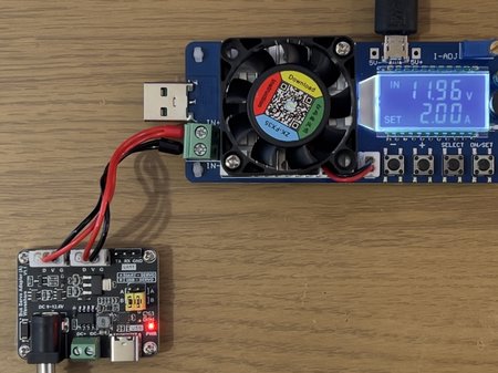
Bench setup used for the 2 A continuous-load tests; a 35 W electronic load draws current through the board’s motor connectors at a regulated 12 V. |
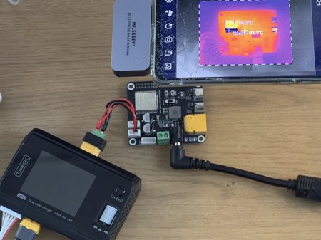
Bench setup used for the higher-current scenarios; an adjustable 500 W LiPo battery charger acts as the load, fed at 12 V from a single bench power supply through the board’s parallel motor connectors. |
Test setup. Left: 2 A load tests; right: 5 / 7 / 10 A load tests.
Throughout all tests, the temperatures of key board components were monitored using a thermal camera to identify potential hotspots and verify safe operating limits.
Waveshare Serial Bus Servo Driver Board
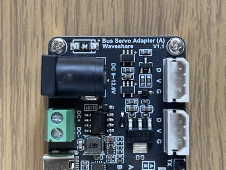
The Waveshare Serial Bus Servo Driver Board is a compact controller designed for Feetech STS and Waveshare ST series serial-bus servos. It features a USB Type-C interface for direct connection to a host PC, making it convenient for development and testing. The board provides two power input options — a 5.5×2.1 mm barrel jack and a screw terminal — offering flexibility depending on the power setup. In addition to the USB interface, it exposes a dedicated UART output, allowing the board to be connected to an external microcontroller for embedded applications.
- Documentation: https://docs.waveshare.com/Bus_Servo_Adapter_A
- Schematic: Bus Servo Adapter (A) Schematic
Revisions
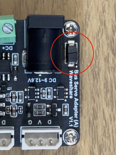
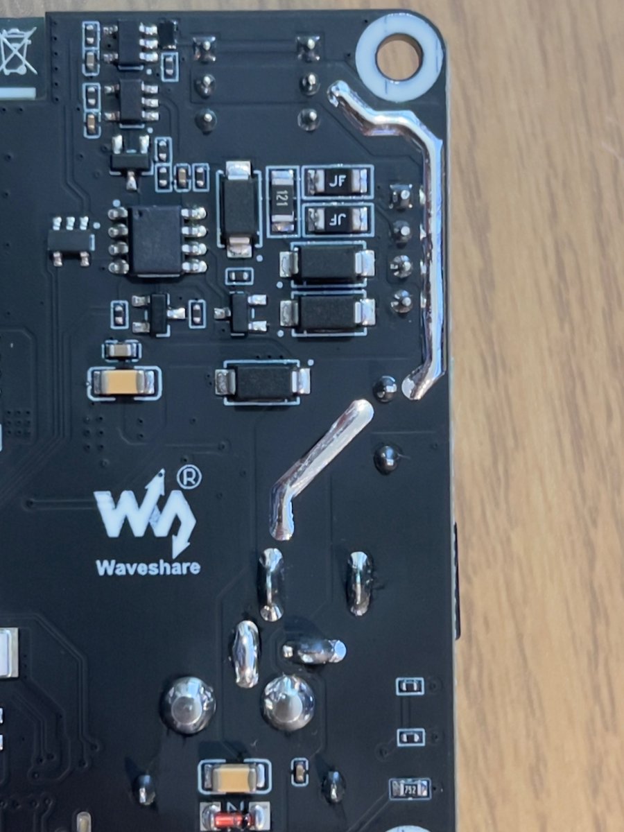
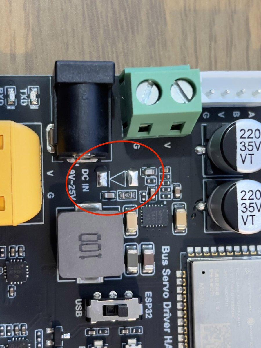
This board has at least two revisions. Revision 1.1 (the latest known revision) includes an extra TVS diode. The diode appears to be relatively sensitive to power quality — with loose or poor power connectors, it may burn out. If the diode burns out, it can be removed completely to restore board functionality.
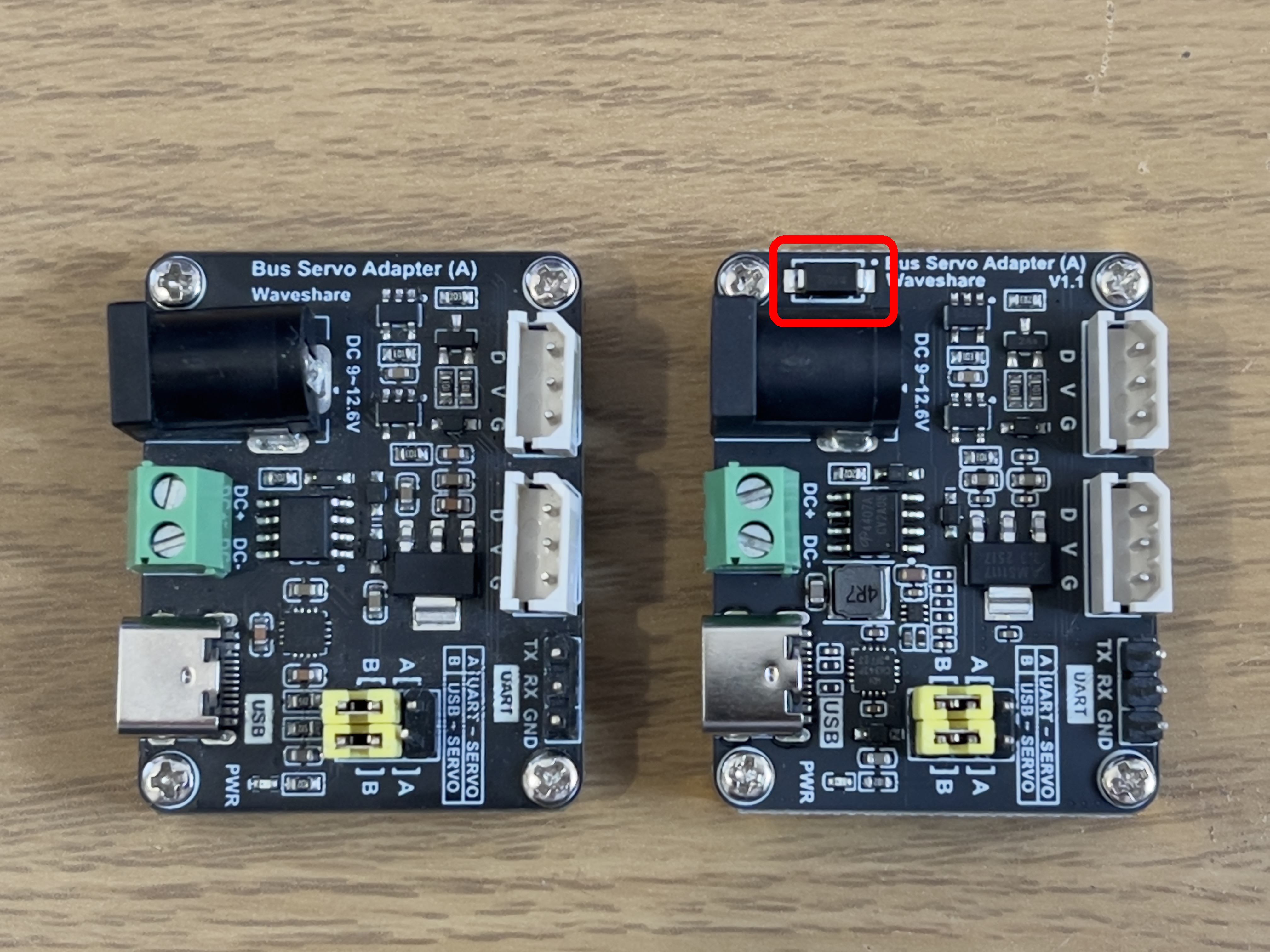
Board revisions side by side: original v1.0 (left) and v1.1 (right). The red rectangle marks the TVS diode added on v1.1.
Close-up of a revision 1.1 board after the TVS diode failed; the burned diode disables the board until physically removed. |
Same board with the failed TVS diode physically removed — the board returns to working order without the protection circuit. |
Board revision 1.1 with a TVS diode. Left: the diode has burned out. Right: the diode was removed to restore functionality.
Power Connectors
The board provides two power input options: a 5.5×2.1 mm barrel jack and a screw terminal. Although both connectors serve the same purpose, they follow slightly different paths on the board, which results in noticeably different behavior under load.
Barrel jack (5.5×2.1 mm): Offers a direct power path to the motor outputs. Both the positive and negative terminals are wired straight to the motor connector pins, with the two motor connectors in parallel. This results in minimal voltage drop and heat generation along the path, making it the more robust option for higher current loads.
Screw terminals (DC+ / DC−): Provide an alternative input method, but introduce additional components in the power path. Instead of feeding the motor outputs directly, the input power is routed through a MOSFET before reaching the motor connectors. Under higher loads, this MOSFET becomes a significant source of heat, which can impact overall efficiency and thermal performance. While the terminals are nominally rated up to 10 A, their relatively small size makes them less suitable for sustained high-current operation in practice.
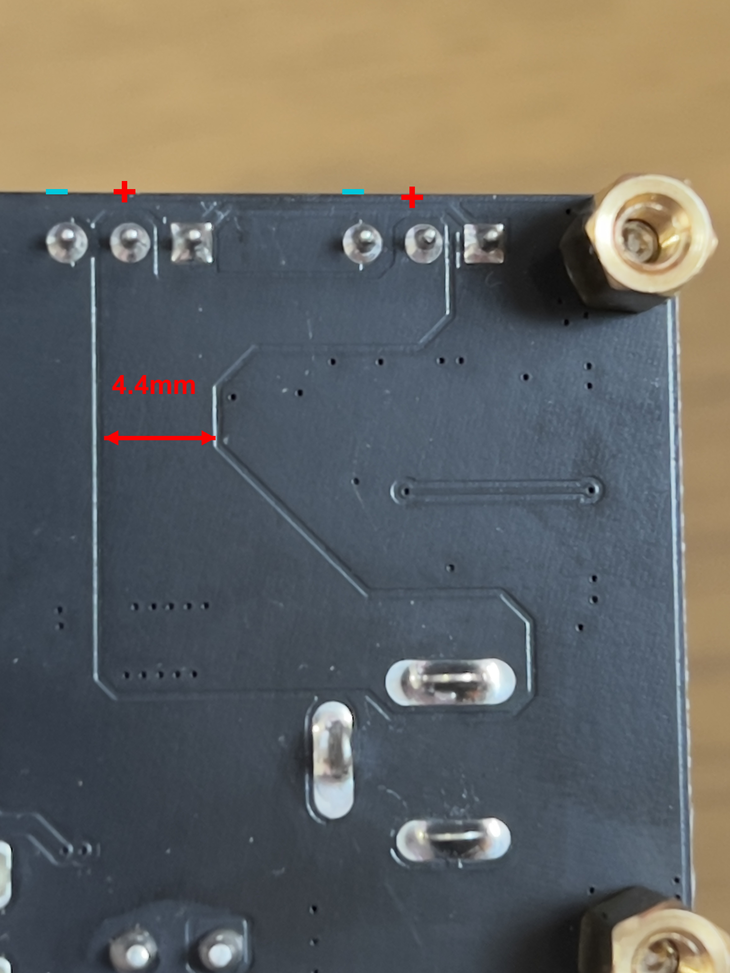
The DC+ copper polygon is 4.4 mm wide and is expected to withstand peak load currents without issues. + / − marks indicate the screw-terminal polarity.
Load Tests
Due to differences in the power circuitry, testing was conducted separately for the barrel jack and screw terminal inputs.
2 A load for 10 minutes
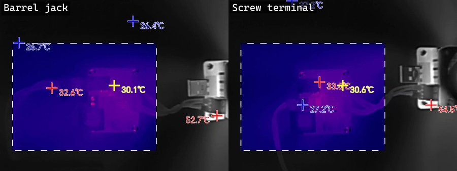
Side-by-side thermal frames near the end of the 2 A / 10 min test. Both paths sit at 30–33 °C — no meaningful difference at this load.
Left: barrel jack. Right: screw terminal.
The 2 A continuous load test showed no issues. The board barely warmed up, with most components remaining close to ambient temperature. Thermal imaging confirmed only minor temperature increases across the board, typically in the range of 30–33 °C, indicating low power losses and efficient current handling under normal operating conditions.
5 A load for 5 minutes
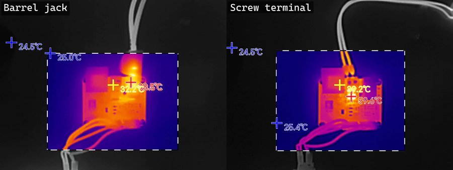
Side-by-side thermal frames near the end of the 5 A / 5 min test. Barrel jack (left): connector ~38–40 °C. Screw terminal (right): MOSFET ~60 °C, the dominant heat source.
Left: barrel jack. Right: screw terminal.
When powered through the barrel jack, the connector itself became noticeably hot, reaching around 38–40 °C. The rest of the board remained relatively cool, with most components staying close to 30–32 °C. This indicates that the primary limitation in this configuration is the connector and its contact resistance, rather than the board’s internal power path.
When using the screw terminals, the thermal behavior was dominated by the onboard MOSFET. Its temperature rose relatively quickly under load and stabilized at around 60 °C after several minutes. Other areas of the board remained moderately warm (30–40 °C). This confirms that, in this configuration, the MOSFET is the main source of power dissipation and heat generation.
Overall, while both input methods handled the 5 A load without immediate failure, they exhibit different thermal bottlenecks: the barrel jack is limited by connector heating, whereas the screw terminal path is limited by MOSFET losses.
7 A load for 2 minutes
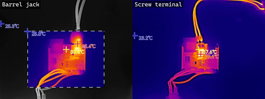
Side-by-side thermal frames at the end of the 7 A / 2 min test. Barrel jack (left): connector ~46 °C. Screw terminal (right): MOSFET ~78–80 °C, approaching the long-term reliability limit.
Left: barrel jack. Right: screw terminal.
When powered through the barrel jack, the connector temperature rose significantly, reaching approximately 45–46 °C. The rest of the board stayed relatively cool (around 34 °C), confirming that the connector itself is the primary thermal bottleneck in this configuration. While the board electronics handled the load well, connector heating becomes more pronounced at higher currents.
In contrast, when using the screw terminals, the MOSFET temperature rose sharply, reaching approximately 78–80 °C — close to the upper limits specified in typical datasheets, where elevated temperature may begin to affect component characteristics and long-term reliability. The terminal wires also became noticeably hot under this load.
Another practical limitation is the size of the screw terminals, which restricts the use of thicker wires and contributes to heating through increased resistance in the wiring.
Overall, at 7 A the system approaches its thermal limits: the barrel jack is constrained by connector heating, while the screw terminal path is limited by MOSFET dissipation and wiring constraints.
10 A for 30 seconds
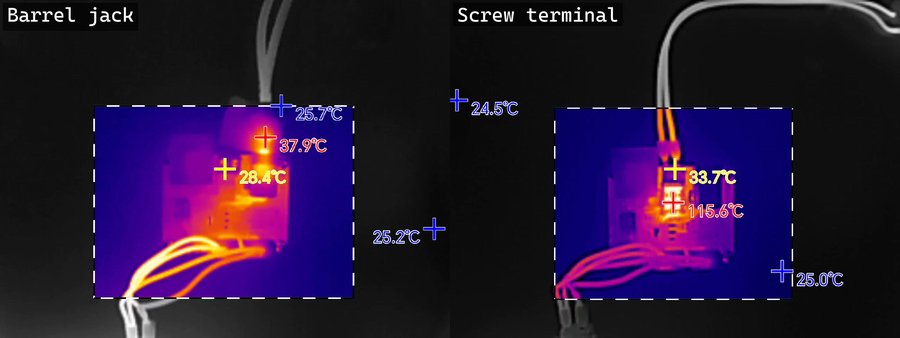
Side-by-side thermal frames at the end of the 10 A / 30 s test. Barrel jack (left): 37.9 °C peak. Screw terminal (right): 115.6 °C on the MOSFET — well beyond safe operating limits.
Left: barrel jack. Right: screw terminal.
The 10 A test (30 seconds) represents an extreme condition and clearly exceeds the comfortable operating range of the board, revealing its failure limits.
When powered through the barrel jack, the main issue shifted to the wiring. The motor wires became noticeably hot under this load, while the board itself remained relatively unaffected. The connector area also showed elevated temperatures (40–45 °C), but no critical hotspots were observed on the PCB. In this configuration, the external wiring becomes the limiting factor before the board itself.
In contrast, the screw terminal path showed severe thermal stress on the MOSFET. Its temperature rapidly exceeded safe operating limits, reaching well above 100 °C (≈120 °C in this test). At this level the device is operating far beyond recommended conditions, where performance degradation, thermal runaway, or permanent damage may occur.
Overall, the results confirm that 10 A operation is not sustainable, particularly when using the screw terminal input. The MOSFET becomes the critical weak point, while in the barrel jack configuration the limitation shifts to connectors and wiring rather than the PCB itself.
Conclusion
The Waveshare Serial Bus Servo Driver Board performs well under typical operating conditions and moderate loads. At 2 A and even 5 A continuous load, the board remains stable and thermally well-behaved, making it suitable for most standard robotics applications.
However, the choice of power input has a significant impact on performance. The barrel jack provides a more direct and efficient power path, with the main limitation being connector and wiring heating at higher currents. In contrast, the screw terminal input introduces a MOSFET into the power path, which becomes the primary source of heat and a clear bottleneck under load.
At higher currents (7 A and above), both configurations begin to approach their thermal limits. The barrel jack is constrained by connector heating, while the screw terminal path is limited by MOSFET dissipation and wiring constraints. Under extreme conditions (10 A), the board operates outside its safe limits — particularly when using the screw terminals, where the MOSFET temperature exceeds safe operating ranges.
An additional reliability concern is the TVS diode present on revision 1.1 boards. Several boards failed during testing, most likely due to power instability or transient conditions. In these cases the TVS diode appeared to fail (burn out), effectively disabling the board. While removing the failed diode can restore functionality, this behavior suggests the protection circuit may be overly sensitive — or not sufficiently robust — for unstable power environments.
In practical terms, the board is well-suited for systems operating up to ~5 A continuous load, with occasional short peaks. For higher loads, careful attention must be paid to power quality, wiring, and connector selection. Whenever possible, the barrel jack input is the preferable option for higher-current applications, while the screw terminals are better suited for lower-current or convenience-focused setups.
Overall, the board offers a good balance of functionality and cost, but its power handling and robustness are limited by connector design, power path implementation, and sensitivity to power transients.
Waveshare Serial Bus Driver HAT
- Documentation: https://www.waveshare.com/wiki/Bus_Servo_Driver_HAT_(A)
- Schematic: Bus Servo Driver HAT (A) Schematic/Bus_Servo_Driver_HAT_(A)_Sch.pdf)
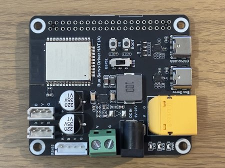
Front of the Waveshare Driver HAT: ESP32 microcontroller, RS485 / TTL output stage, and three power inputs (5.5×2.5 mm barrel jack, screw terminals, XT90). |
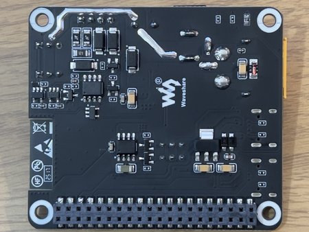
Underside of the Driver HAT showing the 40-pin Raspberry Pi header and the onboard 5 V regulator that feeds the Pi. |
Driver HAT, front (left) and back (right).
The Waveshare Serial Bus Servo Driver HAT is a more advanced and higher-power-oriented solution compared to the simpler adapter board. It integrates an ESP32 microcontroller, allowing it to operate as a standalone controller with both wired and wireless (Wi-Fi / Bluetooth) communication capabilities. The board is designed as a Raspberry Pi HAT, enabling direct connection via the 40-pin header while also providing power to the Pi through an onboard 5 V regulator. It supports both TTL and RS485 servo interfaces, making it compatible with a wider range of serial-bus servos. From a power perspective, the board offers significantly more robust input options, including an XT90 connector and a wide 9–25 V input range.
Power Connectors
The board provides multiple power input options: a 5.5×2.5 mm barrel jack, larger screw terminals (compared to the previous board), and an XT90 connector for high-current applications. All of these connectors are tied to the same power bus, with no additional components — such as MOSFETs — introduced in the power path. This results in a direct, low-resistance connection to the load, which is beneficial for handling higher currents.
All three power inputs feed a single low-resistance power bus with no MOSFET in the path; the larger screw terminals and XT90 connector accept thicker wires for higher-current applications.
The larger screw terminals and the XT90 connector make this board better suited for thicker wires and higher current delivery compared to the smaller connectors used on the previous board.
The PCB has a footprint reserved for a TVS diode, but the diode itself is not populated — transient protection was considered in the design, but is not shipped on this board.
The PCB includes a footprint for a TVS diode, but the diode itself is not populated, suggesting transient protection was considered in the design but is not implemented in the shipped version.
Load Tests
All tests were conducted using the barrel jack input, as all power connectors share the same power path and there is no functional difference between them.
2 A load for 10 minutes
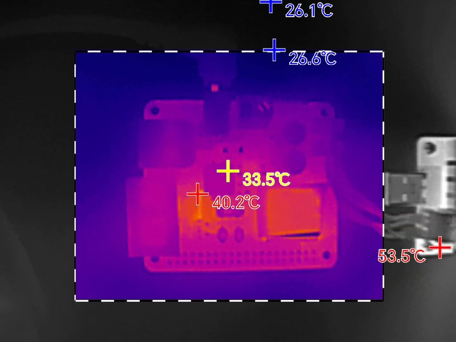
End-of-test thermal frame at 2 A / 10 min. Only the ESP32 module and onboard 5 V regulator show any heating (~33–40 °C); the power path stays cool.
The 2 A load test (10 minutes) showed no thermal concerns. The overall board temperature remained close to ambient, with only minor heating observed.
The only components showing a noticeable temperature rise were the ESP32 module and the onboard voltage regulator, reaching around 33–40 °C. This is expected, as both are actively involved in power regulation and control. No significant heating was observed in the power path or connectors, indicating efficient operation under typical load conditions.
5 A load for 5 minutes
End-of-test thermal frame at 5 A / 5 min. Behavior is essentially identical to the 2 A case — ESP32 and regulator slightly warm, power bus and connectors near ambient.
The 5 A load test (5 minutes) showed similar behavior to the 2 A case, with no significant thermal issues observed. The overall board temperature increased slightly but remained well within safe limits. The primary heat sources were again the ESP32 module and the onboard voltage regulator. The power input path and connectors remained relatively cool, indicating low losses and efficient current handling.
Overall, the board handles 5 A continuous load without any signs of thermal stress, suggesting it is suitable for sustained high-load operation in typical use cases.
7 A load for 2 minutes
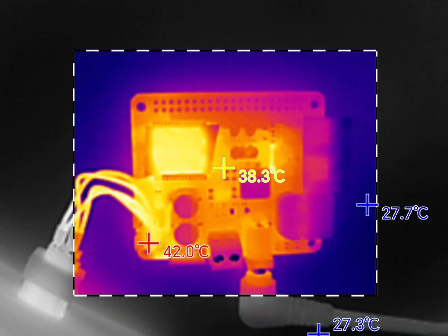
End-of-test thermal frame at 7 A / 2 min. All board components stay within safe range; the only heating worth noting is on the motor wires (~42 °C).
The 7 A load test (2 minutes) showed all board components remained within a safe temperature range. The motor wires became slightly warm, reaching approximately 42.2 °C.
10 A for 30 seconds
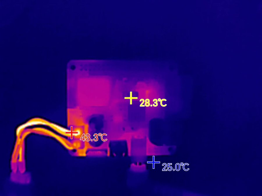
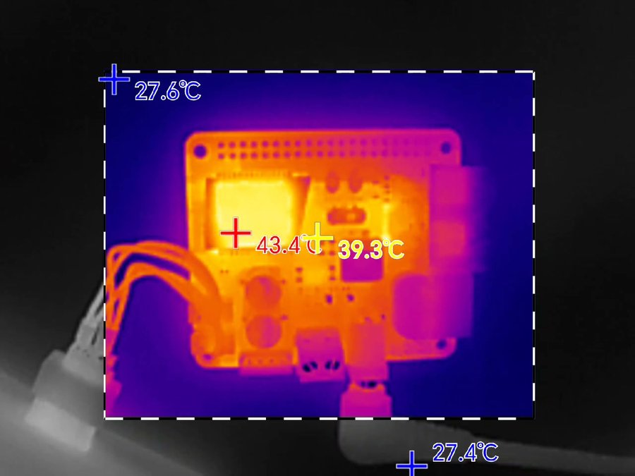
End-of-test thermal frame at 10 A / 30 s. The board itself stays cool — the only noticeable heating is on the motor wires at ~44.6 °C.
During the 10 A load test (30 seconds), all board components remained within safe operating temperatures. The only noticeable heating was in the motor wires, which reached approximately 44.6 °C.
Conclusion
The Waveshare Serial Bus Driver HAT is clearly designed with higher-current applications in mind and performs significantly better under load compared to simpler adapter boards. Across all tests — from 2 A up to 10 A — the board itself remained thermally stable, with no critical hotspots observed in the power path or control circuitry.
Thanks to its direct power-bus design (without additional components such as MOSFETs), the board handles high currents efficiently, and its larger connectors make it well-suited for robust power delivery.
In practice, the limiting factors are not the board itself, but the external components — specifically the motor connectors and stock wiring. As current increases, heating is observed primarily in the wires rather than on the PCB, indicating that the board has sufficient margin while the wiring becomes the bottleneck.
Overall, the HAT is a solid choice for multi-servo systems and high-current setups. It can comfortably handle sustained loads in the 5–7 A range and tolerate short peaks up to 10 A, provided that appropriate wiring and connectors are used.
did the board thermal throttle under sustained load or did it just keep pushing current until something gave?
It kept supplying current without throttling, which is exactly why we flagged it — under sustained high load the regulator got hot enough that we’d add a heatsink and airflow before trusting it in an enclosed build.
really useful load test — the thermal behavior under sustained current is exactly what i wanted to know before picking a driver board