Backlash Compensation in STS3215 Servo Actuators
 3917
3917
This work presents a practical backlash compensation method for Feetech STS3215 servo actuators using a dual-motor configuration with controlled pretension. Experimental results show a reduction of effective output backlash from 14.78 encoder counts (approximately 1.30◦) to 1–2 counts (approximately 0.09◦ to 0.18◦), approaching encoder resolution limits. The method does not require mechanical modification and maintains approximately 80 % of total torque capacity. The technique is suitable for low-cost robotics and educational motion
control systems.
Introduction
The Feetech STS3215 servo has become popular in hobbyist and educational robotics due to its low cost, satisfactory torque output, integrated closed-loop controller, and straightforward serial interface. These characteristics make it attractive for student projects, DIY robotic arms, small mobile manipulators, pan–tilt units, gimbal mechanisms, and general-purpose articulated prototypes where inexpensive but reasonably precise actuation is needed. In such contexts, the STS3215 offers an accessible platform for experimenting with kinematics, feedback control, and embedded motion systems without the cost barriers of industrial-grade actuators.
Despite these advantages, the actuator exhibits several limitations. Because of its multistage gear train, total mechanical backlash is significant: measurements indicate approximately
0.8◦ to 0.9◦ of rotational free play, corresponding to roughly 1.3 mm of motion at a 100 mm lever arm. This level of lost motion degrades positioning accuracy, complicates bidirectional tracking, and limits the usability of the servos in applications requiring precise reversals or high-fidelity control.
The goal of this study is to evaluate simple, implementable methods for reducing the functional impact of backlash when using a paired configuration of STS3215 servos. The work
focuses on practical compensation strategies suitable for low-cost robotic systems, with the aim of improving motion accuracy without hardware modification.
STS3215 Main Features
2.1 Hardware Specifications
The main hardware specifications of the STS3215 servo are summarized in Table 1.
Table 1: STS3215 main hardware specifications.
| Specification | Value |
|---|---|
| Operating (nominal) voltage | 12 V (operating range 4 V to 14 V) |
| Rated torque | 10 kg cm @ 12 V |
| Stall (peak) torque | 30 kg cm @ 12 V |
| Encoder resolution | 12-bit magnetic encoder: 4096 steps over 360° |
| Gear type | Metal gearbox; steel gears and ball bearings |
| Gear ratio | 1 : 345 reduction (12 V, 30 kg cm version) |
2.2 Communication Architecture
The STS3215 uses a half-duplex TTL serial bus, allowing multiple servos to share the same communication line. Servos can be daisy-chained by connecting their signal ports in series. All communication uses the manufacturer’s digital packet protocol, which supports variable-length instruction and status frames.
The communication protocol supports synchronized actuation of multiple servos on the same bus. Through broadcast or group commands, several servos can receive and execute target
updates simultaneously. This capability is essential for coordinated motion, such as paired joint actuation, dual-motor couplings, or experimental setups where timing symmetry between actuators directly affects performance.
2.3 Device Identification and Memory
Each servo contains a unique ID stored in EEPROM. EEPROM parameters are non-volatile and remain stored after power cycles. RAM parameters (e.g., present position, speed, voltage) reset at each boot.
2.4 Main Control Modes
The internal controller supports several operating modes:
1. Position control mode: target position specified in encoder units; configurable speed and acceleration; supports continuous update of the goal position for trajectory tracking.
2. Continuous rotation / speed mode: servo behaves like a motor with speed command, useful for wheels and drive systems.
2.5 Adjustable Parameters
The internal controller exposes a set of parameters that influence performance and safety:
• PID gains (proportional, integral, derivative), which shape servo stiffness, tracking accuracy, and damping.
• Deadband width around the target position; reducing the deadband increases accuracy but may increase oscillation.
• Speed and acceleration limits, including soft-start ramps to prevent overshoot and reduce gear stress.
• Protection options: over-voltage, under-voltage, over-temperature shutdown, over-current/overload protection, torque limit.
• Range and calibration settings: mechanical limits, angle offsets, and zero-position calibration using encoder feedback.
2.6 Feedback and Status Reporting
The servo provides live telemetry including present position (encoder units), speed, load estimate (proportional to current), supply voltage, temperature, and error flags (overload, overheating, voltage error, etc.).
Backlash Compensation with Two Opposed STS3215 Servos
3.1 Mechanical Arrangement
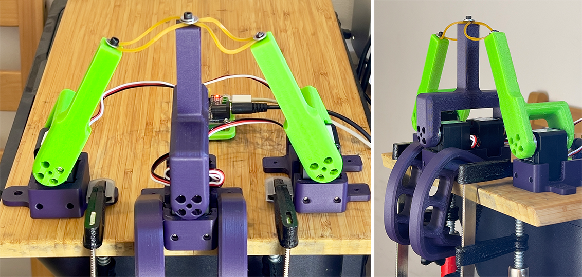
Two STS3215 servos are mounted back-to-back with their output shafts facing opposite directions. The shafts are mechanically coupled using the standard 25T servo horns (the small
stock circular output disks) and a 3D-printed bridging clamp bracket secured with four screws into the horns. This rigid connection ensures accurate shaft alignment and minimizes relative motion between the servos during operation. The two servos are fixed together on a common mounting plate, maintaining their relative orientation and spacing.
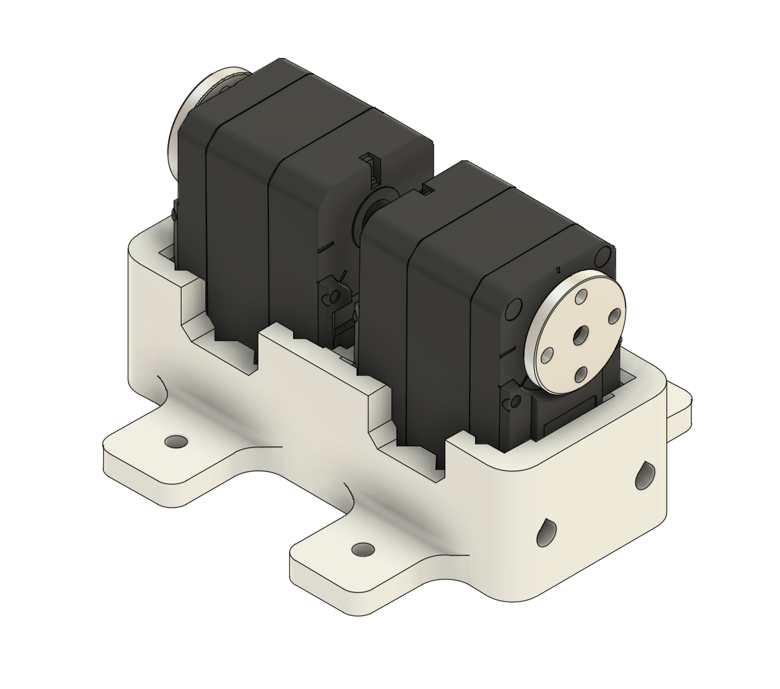
Figure 1: Two STS3215 servos mounted in the holder.
3.2 Control Strategy
Each STS3215 has finite gearbox backlash. When a single motor is commanded to change direction, the output shaft can move a small amount with minimal restoring torque as the
gear teeth transition between flanks. By coupling two motors and biasing them in opposite directions, each motor keeps its gear train loaded on a different flank. The two dead zones no
longer overlap, so the combined system exhibits near-zero play around the commanded angle.
We create that bias by giving the two motors slightly different home positions (a small position offset). At steady state, each motor holds a small position error, producing a steady pretension torque in opposite directions. In this work, the pretension is set to approximately 3 % of stall torque—enough to take up the slack, but small enough to keep current and heat modest.
Figure 2: Two STS3215 servos with attached test bracket and lever.
3.3 Simple Model
Let each motor have a backlash half-width b (in encoder counts), so a single motor has an effective deadzone
$[-b, +b]$
Inside this zone, small changes of commanded position u produce negligible output torque T :
$u \in [-b, b] \Rightarrow T \approx 0$
When two motors are rigidly coupled and we apply an offset d (counts) between their commanded angles, the steady-state torques T1 and T2 pull in opposite directions. If the
magnitude of the offset is larger than the effective deadband,
$|d| > b_{\text{eff}}$ ,
where beff includes the controller deadband and mechanical play, both gear trains remain seated on opposite flanks. The combined closed-loop stiffness around the setpoint becomes approximately the sum of the individual stiffnesses, and the apparent deadzone collapses.
A practical rule from this setup is to choose $|d|$ slightly greater than the deadband but small enough that the resulting holding current remains modest. In our tests, an offset d corresponding to roughly 3 % of stall torque (about 0.9 kg cm for a 30 kg cm servo) worked well. On a 100 mm lever, this torque corresponds to approximately 0.09 kgforce at the tip (about 0.88 N), which is enough to seat the gears without stressing the motor.
3.4 Implementation Steps
1. Zero both motors mechanically (lever centered), with no offsets.
2. Preload one flank: gently rotate the lever clockwise and set Motor 1’s home position.
3. Preload the opposite flank: gently rotate counter-clockwise and set Motor 2’s home/offset so that Motor 2 pushes the other way.
4. Verify current draw at rest and during small dithers; trim the offsets to target approximately 3 % stall torque (or another chosen limit).
Test Setup and Limitations
4.1 Encoder Placement and Backlash Measurement
The STS3215 incorporates its magnetic encoder after the gearbox, directly on the output shaft. This architecture simplifies control but introduces a measurement constraint: the encoder cannot observe motion within the internal gear stages. As a result, true internal backlash cannot be directly measured, because the internal PID loop continuously attempts to drive the shaft to the commanded position.
Within the default deadband range, however, the controller does not correct small deviations, allowing the output shaft to move freely inside the mechanical slack. This characteristic enables an indirect measurement method. When torque is enabled and a small external force is applied to the output lever, the encoder reading changes even though the controller remains within its deadband. Knowing the encoder resolution, these small deviations can be converted into angular displacement, providing an estimate of effective backlash.
4.2 Test Stand
A simple mechanical test stand was constructed to evaluate backlash and the effectiveness of compensation methods. The setup consists of:
1. Primary test motor(s): one or two STS3215 servos serving as the unit under test. A rigid 100 mm lever is mounted to the output shaft to amplify measurable motion.
2. Opposing actuation motors: two additional STS3215 units, each equipped with its own lever, are mounted opposite the primary lever. These “puller” motors apply controlled
forces in clockwise and counter-clockwise directions to displace the primary shaft within its backlash zone.
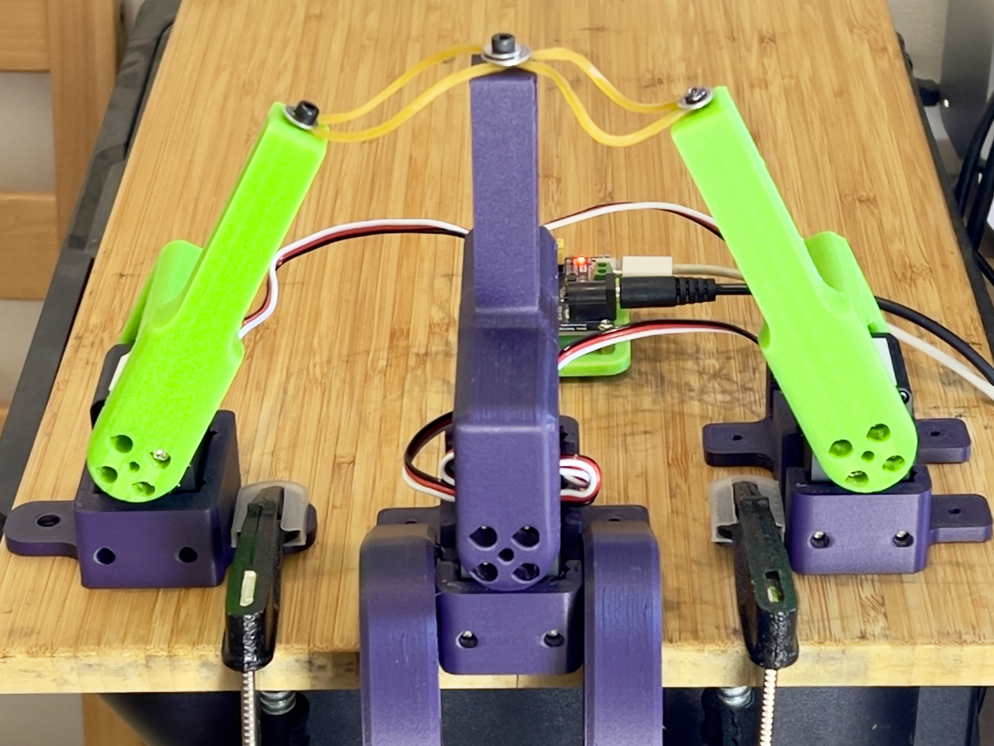
Figure 3: Mechanical test stand used for backlash measurements.
4.3 Opposing-Load Mechanism (Elastic Bands)
To apply a controlled, repeatable counter-torque without introducing extra drivetrain backlash, the two opposing motors pull the main 100 mm lever via elastic bands. The bands are pretensioned so that the measured pull at the lever tip is approximately 0.3 kgforce.
The resulting torque at the lever tip is
$\tau \approx 0.3\,\text{kgf} \times 0.1\,\text{m} \approx 0.294\,\text{N}\cdot\text{m} \approx 3.0\,\text{kg}\cdot\text{cm}$,
which is about 10 % of stall torque (30 kg cm) and 30 % of rated torque (10 kg cm) for a single STS3215 at 12 V. This is high enough to fully seat the gear train in either direction, yet low
enough to avoid saturating the internal controller.
The elastic coupling provides a compliant, backlash-free load path, so backlash in the two opposing motors can be ignored. It also smooths load reversals, reducing shock and motor
current spikes during the back-and-forth sequence.
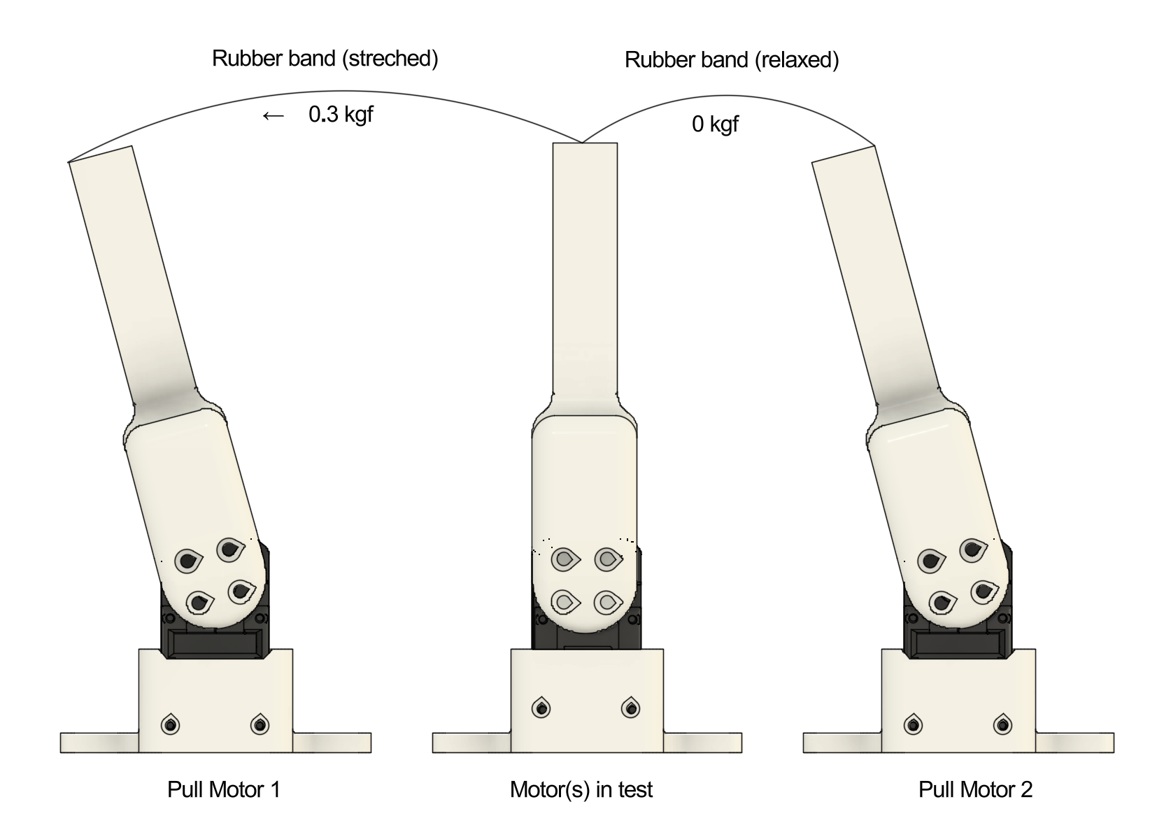
Figure 4: Example test setup. The center motor holds position while the left puller motor applies approximately 0.3 kg force to the lever. The right puller motor is relaxed and does not apply force.
4.4 Force Application Sequence
The primary motor executes a short back-and-forth movement to preload its internal gears in either the clockwise or counter-clockwise direction. Once loaded, the opposing motors alternately pull the lever in opposite directions. Between pulls, they briefly release tension to ensure that no residual force biases the measurement. The entire sequence—preload motions, alternating pulls, and release intervals—is coordinated by custom control code running on the host controller.
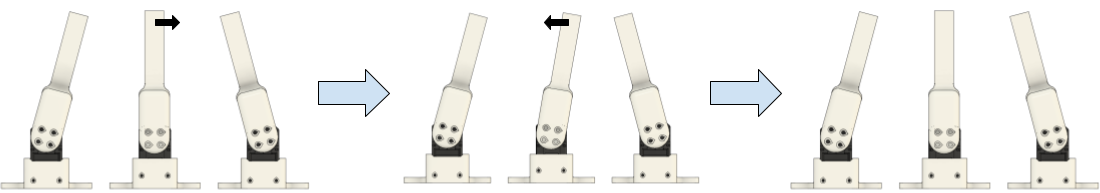
Figure 5: Test sequence, stage 1 (preparation). Both elastic bands are relaxed. The tested motor(s) move in CW or CCW direction and return to the center position, preloading the gears.
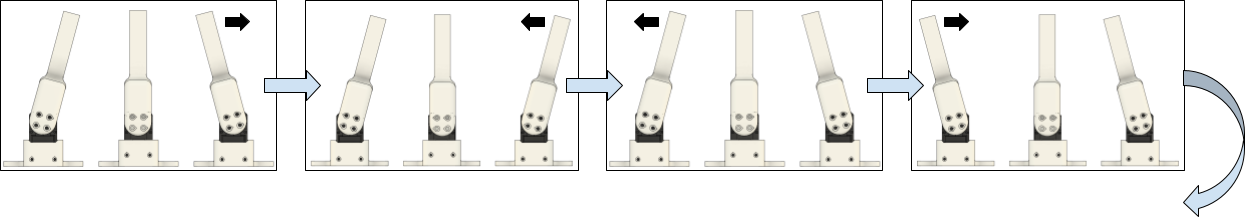
Figure 6: Test sequence, stage 2 (stress). The lever of the tested motor(s) remains in the central position while the pull motors alternately apply load in opposite directions. Between pulls, both elastic bands are relaxed.
4.5 Telemetry Acquisition
All servos stream periodic status data to the host, where custom logging software collects and stores it in CSV format for later analysis. Logged parameters include:
• timestamp,
• present and target positions,
• load/torque estimate and current consumption.
A Python post-processing script visualizes the motion profiles and computes effective backlash by analyzing position deviations caused by the alternating external forces.
4.6 Limitations
Several limitations should be noted:
• Because the encoder is placed after the gearbox, only output backlash can be observed; internal gear-stage behavior remains unmeasured.
• The internal PID deadband interacts with the measurement method: too small a deadband causes the controller to fight the applied force, whereas too large a deadband reduces measurement resolution. The default deadband setting is used here.
• Over the small displacements used for backlash probing, elastic band force change is minimal but not zero, introducing a small nonlinearity.
Results and Analysis
5.1 Quantities and Conversions
With a 12-bit encoder, one revolution corresponds to 4096 counts, so one count is
$\Delta\theta = \frac{360°}{4096} \approx 0.0879°$
At a radius of 100 mm, the corresponding linear displacement per count is
$\Delta x \approx 0.0879° \times \frac{\pi}{180°} \times 100\,\text{mm} \approx 0.153\,\text{mm}$
5.2 Backlash Measurement Procedure
As part of each test, a sequence of motions is executed according to the force application sequence described above. During this sequence, motor telemetry (including each servo current
position and target position) is sampled at approximately 10 Hz rate. For each cycle, two reference conditions are extracted:
• Loaded reference: the actual encoder position while the pull motors apply a nominal 0.3 kgforce to the lever in one direction.
• Unloaded reference: the actual encoder position immediately after both pull motors have relaxed and no external force is applied to the main lever.
For each pull direction (CW and CCW), two reference points are extracted from the telemetry stream:
• Unloaded (relaxed) state: the actual encoder position immediately after both pull motors release tension.
• Loaded (stretched) state: the actual encoder position while the approximately 0.3 kgforce is applied in that direction.
For each of these states, multiple samples are collected over the repeated motion cycles. The samples are averaged to obtain stable estimates of:
• $p_{\text{cw,unloaded}}$
• $p_{\text{ccw,unloaded}}$
• $p_{\text{cw,loaded}}$
• $p_{\text{ccw,loaded}}$
The total positional deviation between the two pull directions is then computed separately for the unloaded and loaded conditions:
$d_{\text{unloaded}} = |p_{\text{cw,unloaded}} – p_{\text{ccw,unloaded}}|$ , (1)
$d_{\text{loaded}} = |p_{\text{cw,loaded}} – p_{\text{ccw,loaded}}|$ . (2)
These two values represent the measured backlash in the absence of external force and under the applied counter-torque, respectively. Since the motion sequence is repeated multiple times, a sufficient number of samples is collected to compute the average backlash and its dispersion for each configuration (single motor, dual motor, dual motor with preload).
5.3 Single STS3215 Servo with Default Settings
Before evaluating dual-motor compensation methods, the backlash of a single STS3215 servo was measured to establish a baseline. The motor was mounted rigidly, driven to a fixed target position (2047 counts), and subjected to the standard force-application sequence.
For the single STS3215, the measured position deviation between CW and CCW loading was:
• Loaded state: 14.78 counts,
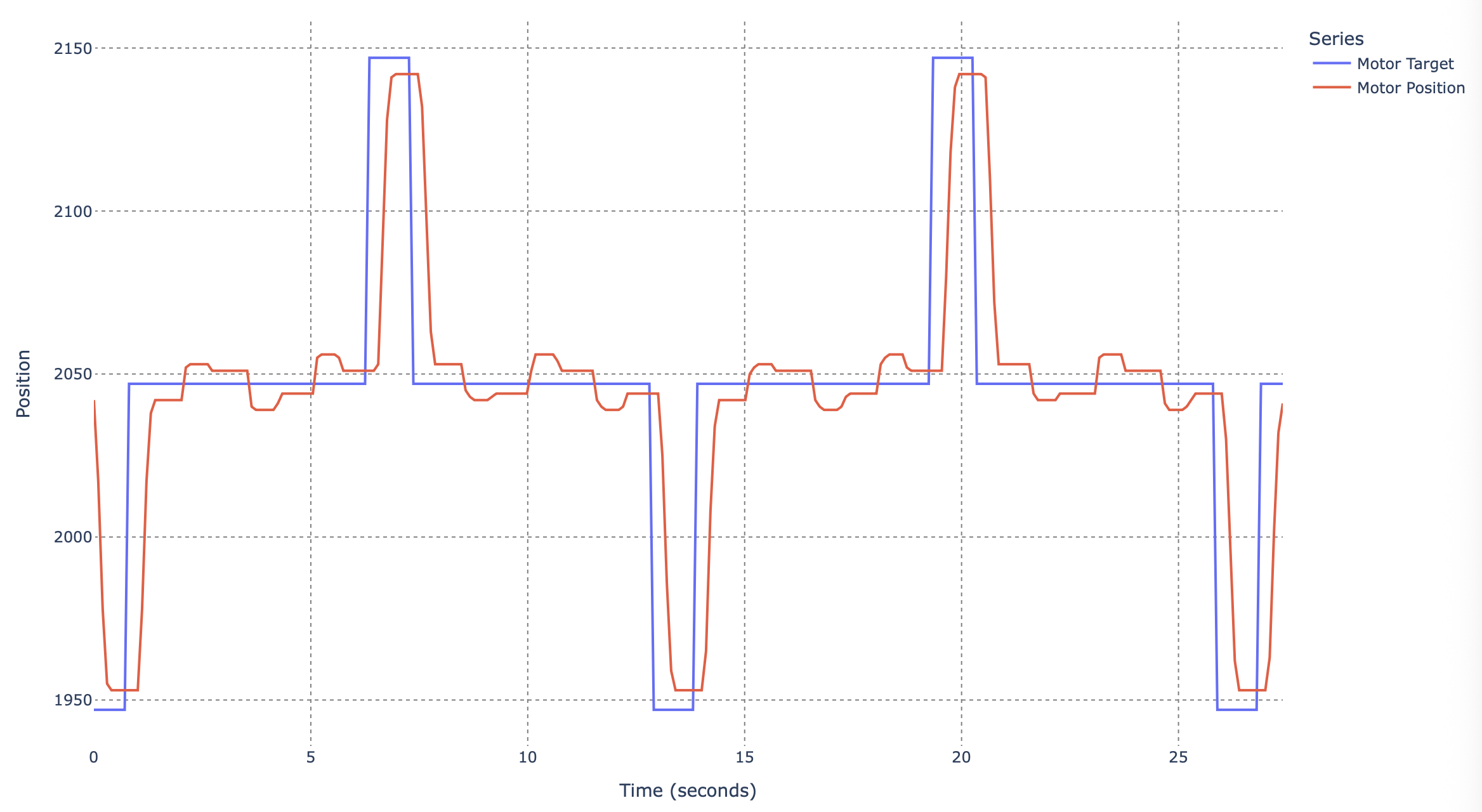
Figure 7: Test results for a single STS3215 servo with default settings under alternating external load.
• Unloaded (relaxed) state: 7.03 counts.
These correspond to:
• Loaded backlash: ≈ 1.30◦ or ≈ 2.27 mm at 100 mm radius,
• Unloaded backlash: ≈ 0.62◦ or ≈ 1.08 mm at 100 mm radius.
These results confirm that a single STS3215 exhibits on the order of 1–2 mm of effective backlash at a 100 mm lever radius, increasing under load.
5.4 Coupled STS3215 Servos with Default Settings
To evaluate the effect of mechanically coupling two STS3215 servos, the motors were first tested in a rigid back-to-back configuration without applying any positional offset or deliberate pretension. Both actuators were commanded to the same target position and driven synchronously, sharing a common output through the fixed bracket assembly.
With two STS3215 servos rigidly coupled and commanded to the same target position, the effective backlash is reduced compared to a single actuator. From the averaged data, the total
position deviation between CW and CCW loading is:
Loaded (approximately 3 kg cm):
• Servo 1: 7.50 counts ≈ 0.66◦ ≈ 1.15 mm at 100 mm radius,
• Servo 2: 8.00 counts ≈ 0.70◦ ≈ 1.23 mm at 100 mm radius.
Unloaded:
• Servo 1: 6.00 counts ≈ 0.53◦ ≈ 0.92 mm,
• Servo 2: 6.00 counts ≈ 0.53◦ ≈ 0.92 mm.
Simply coupling two STS3215s back-to-back approximately halves the loaded backlash compared to the single-motor case, even before applying explicit compensation.
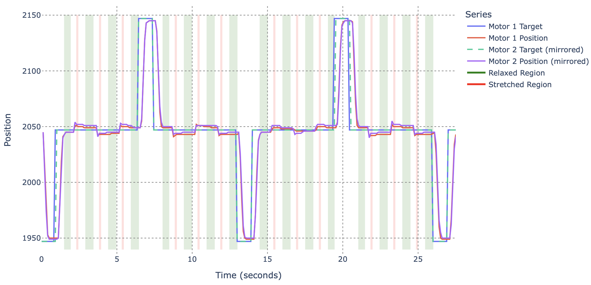
Figure 8: Test results for two coupled STS3215 servos with default settings. Highlighted regions indicate intervals with relaxed and stretched elastic bands. Red and blue curves denote measured positions of Servo 1 and Servo 2; the dashed line shows the commanded target position.
5.5 Coupled STS3215 Servos with Home Position Offset
To further reduce residual backlash, a controlled home-position offset was introduced between the two coupled STS3215 units. The lever assembly was manually rotated to preload the gear train of one motor in the CW direction, and this position was stored as its home reference. The lever was then rotated in the opposite direction to preload the second motor in CCW, and its home position was recorded accordingly. This procedure establishes a small, constant pretension torque between the servos, ensuring that both gear trains remain seated on opposite flanks.
With the home-position offset (pretension) applied, the measured position deviation is:
Loaded (approximately 3 kg cm):
• Servo 1: 0 counts,
• Servo 2: 2 counts ≈ 0.18◦ ≈ 0.31 mm at 100 mm radius.
Unloaded:
• Servo 1: 0 counts,
• Servo 2: 1 count ≈ 0.088◦ ≈ 0.15 mm at 100 mm radius.
With a small home-position offset that preloads the two servos against opposite gear flanks, the apparent backlash is reduced to 1–2 encoder counts, i.e., on the order of the encoder’s
own resolution (approximately 0.09◦ to 0.18◦, 0.15 mm to 0.31 mm at 100 mm radius). This is a very significant improvement over the single-motor case and a clear improvement over the uncompensated dual-motor configuration.
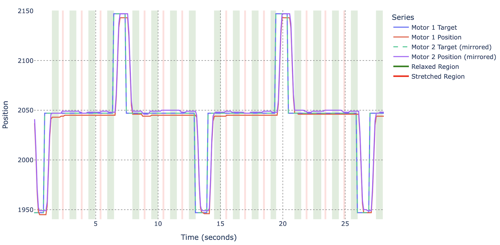
Figure 9: Test results for two coupled STS3215 servos with backlash compensation via home-position offset. Red and blue curves denote Servo 1 and Servo 2; the dashed line shows the commanded position. Highlighted regions indicate relaxed and stretched load intervals.
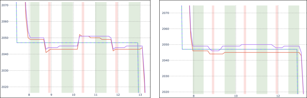
Figure 10: Position deviation comparison for coupled servos. Left: configuration with default settings (no compensation). Right: configuration with home-position offset providing pretension.
5.6 Results Summary
To enable direct comparison among all test configurations, backlash values for both loaded (L) and unloaded (U) conditions were compiled into a single results table. For dual-motor setups, the larger (worst-case) deviation between the two servos is used to represent system backlash.
Table 2: Combined backlash test results. U: unloaded (measured immediately after both pulling motors relax). L: loaded (measured while the 0.3 kgforce counter-force is applied). Backlash is expressed in encoder counts, angular displacement, and linear displacement at a 100 mm radius. For two-motor setups, the larger of the two measured deviations is reported.
| Configuration | Backlash (counts) | Backlash (deg) | Backlash (mm) |
|---|---|---|---|
| Single motor (U) | 7.03 | 0.62 | 1.07 |
| Single motor (L) | 14.78 | 1.30 | 2.26 |
| Coupled, no compensation (U) | 6.00 | 0.53 | 0.92 |
| Coupled, no compensation (L) | 8.00 | 0.70 | 1.22 |
| Coupled, offset compensation (U) | 1.00 | 0.09 | 0.15 |
| Coupled, offset compensation (L) | 2.00 | 0.18 | 0.31 |
Conclusions
The experiments confirm that mechanical backlash in STS3215 servos can be effectively minimized through a dual-actuator configuration. By coupling two motors and introducing a small positional offset, both gear trains remain preloaded against opposite flanks, effectively eliminating the free-motion zone. The resulting system maintains approximately 80 % of the combined torque capacity of both servos, indicating only minor efficiency losses while achieving near-zero measurable backlash.
Thermal monitoring showed no overheating or abnormal current draw, suggesting that the applied pretension remains within safe limits for continuous operation. This simple, low-cost
compensation method significantly improves positioning accuracy and rigidity using standard hobby-grade components, making it well suited for robotics studies, educational applications, and precision motion experiments.
Future Work
Future work may include dynamic backlash compensation, where the pretension or position offset is adjusted in real time based on torque feedback or direction of motion. It would also be valuable to study the influence of mechanical coupling stiffness, including bracket material and geometry, on system behavior.
Additional tests with different servo models, gear ratios, and control tunings could help generalize the method and quantify its limits in higher-load or high-speed applications.
Appendix: Code and Supplementary Materials
Custom control code for the dual-servo compensation system, mechanical design files (CAD models), test stand schematics, and post-processing scripts are available at:
GitHub repository: https://github.com/roboninecom/Measuring-Backlash-in-Popular-UART-Servos
does feedforward compensation actually help here or does the encoder error swamp it?
Feedforward helps for the deterministic part of the backlash — the directional offset — but you’re right that the encoder being motor-side limits how much you can correct, because you can’t directly observe the output position. It reduces the error, it doesn’t eliminate it.
Thank you for explaining.
clever firmware trick with the directional offset table, hadnt seen that approach before
software comp only gets you so far when the encoder is on the motor side not the output, this is the core problem
honestly the most realistic take ive read, most posts pretend you can software your way out of mechanical slop entirely and you just cant, this one admits the limits